Infinity supported application 7 – AEM Infinity Supported Applications - GM LSX 58X Engine User Manual
Page 7
Infinity Supported Application
7
© 2014 AEM Performance Electronics
Infinity
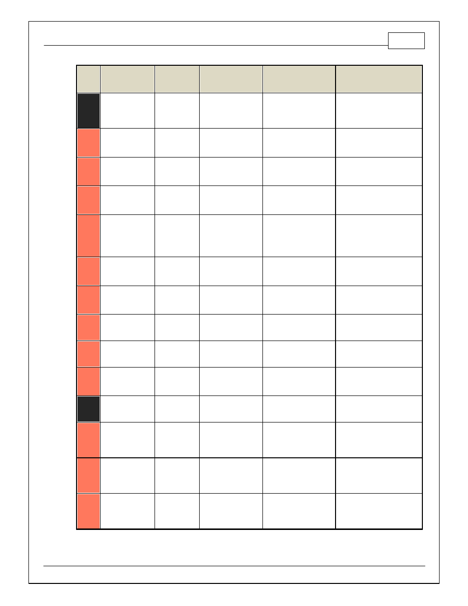
Pin
Hardware
Reference
7100-XXXX-62
7101-XXXX-63
Function
Dest. Pin GM LS
Hardware Specification
Notes
C1-20
AGND_1
Sensor Ground
Mass Airf low (incl IAT
sensor) Sensor Ground/
Engine Coolant Temp
Sensor Ground
Dedicated analog ground
Analog 0–5V sensor ground
C1-21
Crankshaf t Position
Sensor Hall
Crankshaf t
Position Sensor
Hall
CKP Sensor Signal
10K pullup to 12V. Will work
with ground or f loating
switches.
See Setup Wizard page Cam/
Crank f or options.
C1-22
Camshaf t Position
Sensor 1 Hall
Camshaf t
Position Sensor
1 Hall
CMP Sensor Signal
10K pullup to 12V. Will work
with ground or f loating
switches.
See Setup Wizard page Cam/
Crank f or options.
C1-23
Digital_In_2
Camshaf t
Position Sensor
2 Hall
Mass Air Flow Sensor
(Digital) Signal
10K pullup to 12V. Will work
with ground or f loating
switches.
See Setup Wizard page Cam/
Crank f or options.
C1-24
Digital_In_3
Turbo Speed Hz
10K pullup to 12V. Will work
with ground or f loating
switches.
See Setup Wizard page Input
Function Assignment f or
calibration constant. TurboSpeed
[RPM] = Turbo [Hz] * Turbo Speed
Calibration.
C1-25
Digital_In_4
Vehicle Speed
Sensor
10K pullup to 12V. Will work
with ground or f loating
switches.
See Setup Wizard page Input
Function Assignment f or
calibration constant.
C1-26
Digital_In_5
Flex Fuel
10K pullup to 12V. Will work
with ground or f loating
switches.
See channel FlexDigitalIn [Hz] f or
raw f requency input data.
C1-27
Knock Sensor 1
Knock Sensor 1
Knock Sensor 1 Signal
Dedicated knock signal
processor
See Setup Wizard page Knock
Setup f or options.
C1-28
Knock Sensor 2
Knock Sensor 2
Knock Sensor 2 Signal
Dedicated knock signal
processor
See Setup Wizard page Knock
Setup f or options.
C1-29
+12V_Relay _Control
+12V Relay
Control
See Main Relay /Fuel
Pump Schematic
0.7A max ground sink f or
external relay control
Will activ ate at key on and at
key of f according to the
conf iguration settings.
C1-30
Power Ground
Ground
Power Ground
Connect directly to battery
ground.
C1-31
CANL_Aout
AEMNet CANL
Dedicated High Speed CAN
Transceiv er
Recommend twisted pair (one
twist per 2") with terminating
resistor. Contact AEM f or
additional inf ormation.
C1-32
CANH_Aout
AEMNet CANH
Dedicated High Speed CAN
Transceiv er
Recommend twisted pair (one
twist per 2") with terminating
resistor. Contact AEM f or
additional inf ormation.
C1-33
LowsideSwitch_1
Boost Control
Lowside switch, 4A max
with internal f ly back diode.
Inductiv e load should NOT
hav e f ull time power.
See Setup Wizard page Boost
Control f or options. Monitor
BoostControl [%] channel f or
output state.