Pinouts, Infinity pinouts, Infinity supported application 5 – AEM Infinity Supported Applications - GM LSX 58X Engine User Manual
Page 5
Infinity Supported Application
5
© 2014 AEM Performance Electronics
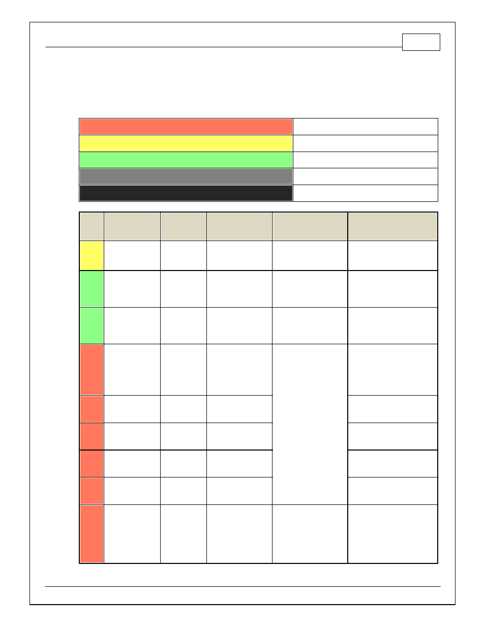
PINOUTS
Infinity Pinouts
Dedicated
Dedicated and not reconfigurable
Assigned
Assigned but reconfigurable
Available
Available for user setup
Not Applicable
Not used in this configuration
Required
Required for proper function
Infinity
Pin
Hardware
Reference
7100-XXXX-62
7101-XXXX-63
Function
Dest. Pin GM LS
Hardware Specification
Notes
C1-1
LowsideSwitch_4
A/C Relay
Control
A/C Clutch Relay Ctrl
Lowside switch, 4A max,
NO internal f ly back diode.
See Setup Wizard "LowSide
Assignment Tables" f or output
assignment
C1-2
LowsideSwitch_5
LS5
Lowside switch, 4A max
with internal f ly back diode.
Inductiv e load should NOT
hav e f ull time power.
See Setup Wizard Page "LowSide
Assignment Tables" f or output
assignment and 2D table
"LS5_Duty [%]" f or activ ation.
C1-3
LowsideSwitch_6
LS6
Lowside switch, 4A max
with internal f ly back diode.
Inductiv e load should NOT
hav e f ull time power.
See Setup Wizard Page "LowSide
Assignment Tables" f or output
assignment and 2D table
"LS6_Duty [%]" f or activ ation.
C1-4
UEGO 1 Heat
UEGO 1 Heat
Bosch UEGO controller
Lowside switch f or UEGO heater
control. Connect to pin 4 of
Bosch UEGO sensor. NOTE that
pin 3 of the Sensor is heater (+)
and must be power by a f used/
switched 12V supply .
C1-5
UEGO 1 IA
UEGO 1 IA
Trim Current signal. Connect to
pin 2 of Bosch UEGO sensor.
C1-6
UEGO 1 IP
UEGO 1 IP
Pumping Current signal. Connect
to pin 6 of Bosch UEGO sensor.
C1-7
UEGO 1 UN
UEGO 1 UN
Nernst Voltage signal. Connect to
pin 1 of Bosch UEGO sensor.
C1-8
UEGO 1 VM
UEGO 1 VM
Virtual Ground signal. Connect to
pin 5 of Bosch UEGO sensor.
C1-9
Flash_Enable
Flash Enable
10K pulldown
Not usually needed f or automatic
f irmware updates through Inf inity
Tuner. If connection errors occur
during update, connect 12 v olts
to this pin bef ore proceeding with
upgrade. Disconnect the 12 v olts
signal af ter the update.