AEM Infinity Supported Applications - GM LSX 58X Engine User Manual
Page 14
14
© 2014 AEM Performance Electronics
Infinity
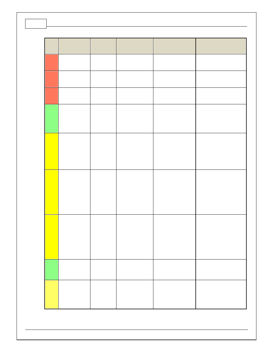
Pin
Hardware
Reference
7100-XXXX-62
7101-XXXX-63
Function
Dest. Pin GM LS
Hardware Specification
Notes
C2-30
AGND_2
Sensor Ground
Knock Sensor 1
Ground/ Knock Sensor
2 Ground
Dedicated analog ground
Analog 0–5V sensor ground
C2-31
AGND_2
Sensor Ground
Cam Position Sensor
Ground/ Crank Position
Sensor Ground
Dedicated analog ground
Analog 0–5V sensor ground
C2-32
AGND_2
Sensor Ground
MAP Sensor Ground/
A/C Pressure Sensor
Ground
Dedicated analog ground
Analog 0–5V sensor ground
C2-33
Analog_In_20
Spare Analog
Input
12 bit A/D, 100K pullup to
5V
0–5V analog signal. Use +5V Out
pins as power supply and Sensor
Ground pins as the low ref erence.
Do not connect signals
ref erenced to +12V as this can
permanently damage the ECU.
C2-34
Analog_In_21
3 Step Enable
Switch
12 bit A/D, 100K pullup to
5V
0–5V analog signal. Use +5V Out
pins as power supply and Sensor
Ground pins as the low ref erence.
Do not connect signals
ref erenced to +12V as this can
permanently damage the ECU.
See 3StepSwitch 1-axis table f or
setup.
C2-35
Analog_In_22
USB Logging
Activ ate
12 bit A/D, 100K pullup to
5V
0–5V analog signal. Use +5V Out
pins as power supply and Sensor
Ground pins as the low ref erence.
Do not connect signals
ref erenced to +12V as this can
permanently damage the ECU.
See USBLoggingRequestIn
channel f or input state. See
Setup Wizard page USB Logging
f or conf iguration options.
C2-36
Analog_In_23
Charge Out
Pressure
12 bit A/D, 100K pullup to
5V
0–5V analog signal. Use +5V Out
pins as power supply and Sensor
Ground pins as the low ref erence.
Do not connect signals
ref erenced to +12V as this can
permanently damage the ECU.
See ChargeOutPress [kPa]
channel f or input state. See
Setup Wizard page Charge Out
Pressure f or calibration options.
C2-37
Digital_In_6
Spare Digital
Input
No pullup. Will work with
TTL signals.
Input can be assigned to dif f erent
pins. See Setup Wizard page
Input Function Assignments f or
input mapping options.
C2-38
Digital_In_7
Clutch Switch
No pullup. Will work with
TTL signals.
See ClutchSwitch 1-axis table f or
setup options. Input can be
assigned to dif f erent pins. See
Setup Wizard page Input Function
Assignments f or input mapping
options.