Infinity supported application 13 – AEM Infinity Supported Applications - GM LSX 58X Engine User Manual
Page 13
Infinity Supported Application
13
© 2014 AEM Performance Electronics
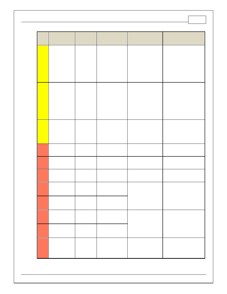
Infinity
Pin
Hardware
Reference
7100-XXXX-62
7101-XXXX-63
Function
Dest. Pin GM LS
Hardware Specification
Notes
C2-19
Analog_In_14
Traction Control
Mode /
Sensitiv ity
12 bit A/D, 100K pullup to
5V
0–5V analog signal. Use +5V Out
pins as power supply and Sensor
Ground pins as the low ref erence.
Do not connect signals
ref erenced to +12V as this can
permanently damage the ECU.
See the TC_SlipTrgtTrim [MPH] 1-
axis table. A multi-position rotary
switch such as AEM P/N 30-2056
is recommended.
C2-20
Analog_In_15
Exhaust Back
Pressure
12 bit A/D, 100K pullup to
5V
0–5V analog signal. Use +5V Out
pins as power supply and Sensor
Ground pins as the low ref erence.
Do not connect signals
ref erenced to +12V as this can
permanently damage the ECU.
See Setup Wizard Exhaust
Pressure page f or setup options.
See EBPress [kPa] f or channel
data.
C2-21
Analog_In_16
DBW1_TPSB
[%]
12 bit A/D, 100K pullup to
5V
0–5V analog signal. Use +5V Out
pins as power supply and Sensor
Ground pins as the low ref erence.
Do not connect signals
ref erenced to +12V as this can
permanently damage the ECU.
C2-22
+5V_Out_2
+5V Out
TP Sensor 1 +5V
Regulated, f used +5V
supply f or sensor power
Analog sensor power
C2-23
+5V_Out_2
+5V Out
MAP Sensor +5V
Regulated, f used +5V
supply f or sensor power
Analog sensor power
C2-24
+5V_Out_2
+5V Out
A/C Pressure Sensor
+5V
Regulated, f used +5V
supply f or sensor power
Analog sensor power
C2-25
VR+_In_5
Driv en Right
Wheel Speed
Sensor +
Dif f erential Variable
Reluctance Zero Cross
Detection
See Driv en Wheel Speed
Calibration in the Setup Wizard
Input Function Assignment page.
C2-26
VR-_In_5
Driv en Right
Wheel Speed
Sensor -
C2-27
VR-_In_4
Non Driv en
Right Wheel
Speed Sensor -
Dif f erential Variable
Reluctance Zero Cross
Detection
See Non Driv en Wheel Speed
Calibration in the Setup Wizard
Input Function Assignment page.
C2-28
V R+_In_4
Non Driv en
Right Wheel
Speed Sensor +
C2-29
LowsideSwitch_9
Tachometer
Lowside switch, 4A max
with internal f ly back diode,
2.2K 12V pullup. Inductiv e
load should NOT hav e f ull
time power.
See Setup Wizard page Tacho f or
conf iguration options.