Wideband failsafe configuration – AEM 30-4900 Wideband Failsafe Gauge User Manual
Page 6
Page 7
7. Install USB cable so the PC end of the cable is easily accessible and route the gauge end of cable to
the gauge mounting location. USB cable is meant to be permanently installed to gauge and left in
vehicle. Stow PC end of cable in location such as glove box or center console, etc.
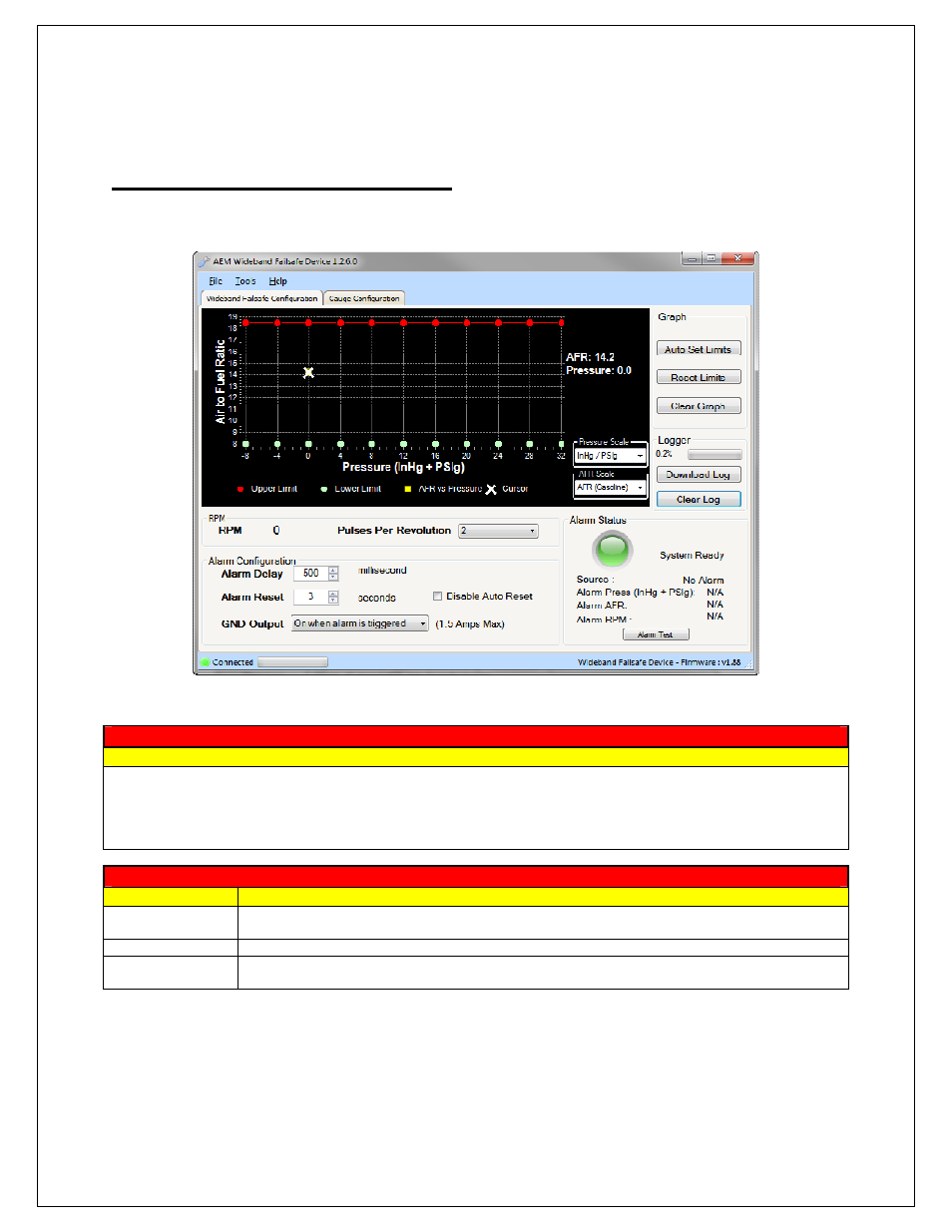
Wideband Failsafe Configuration
In this tab, the AFR monitoring and alarm output functionality of the Wideband Failsafe can be configured.
Air to Fuel Ratio vs. Pressure
Description
Displays AFR vs. Pressure data points. AFR points will be populated live whenever the PC is connected to the
Wideband Failsafe and the UEGO sensor is registering an input. The current AFR and Pressure values are shown
live on the right side of the graph. The graph area is where the high and low AFR limit lines are established.
Configure the pressure scale and AFR scale before setting the boundary lines as they will reset each time a different
scale is selected.
Graph
Button
Description
Auto Set Limits
Automatically sets the upper and lower AFR lines based on an average of the collected AFR
data points
Reset Limits
Resets the upper AFR limit line to maximum and the lower AFR limit line to minimum
Clear Graph
Clears all the displayed AFR data points from the graph; does not clear stored AFR data from
logger