AEM 30-4900 Wideband Failsafe Gauge User Manual
Page 11
Page 12
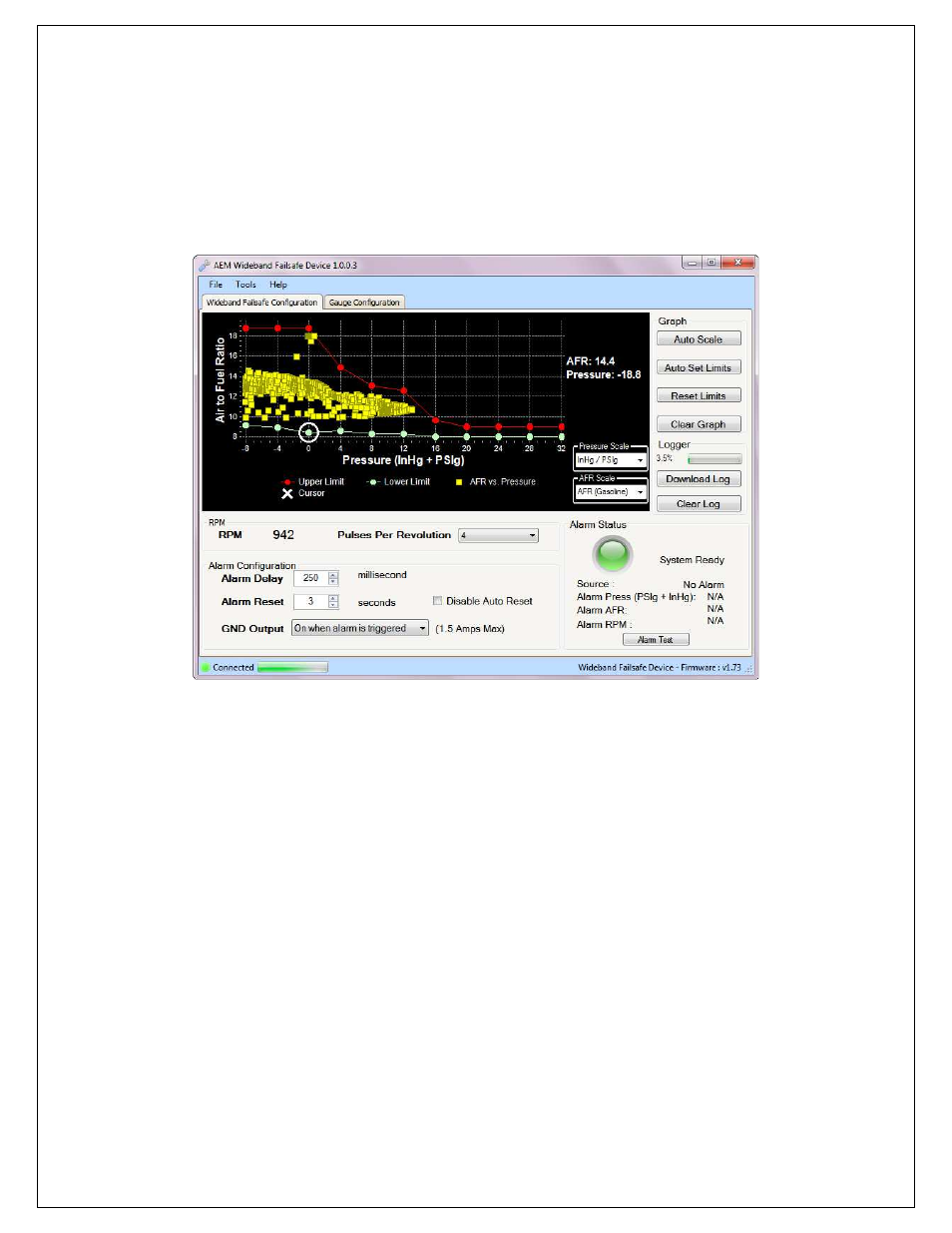
4. With a baseline AFR curve now established, click on Auto Set Limits and the software will
produce its best suggested high and low AFR limit lines based on the populated AFR data shown
on the graph. Review and adjust the high and low AFR limit lines as needed to contour the lines
around the baseline AFR curve (shown below). This can be done by clicking on a breakpoint and
either dragging up or down with the mouse or by clicking the up and down arrows on the
keyboard. To move to the next breakpoint, click on it with the mouse or use the right and left
arrows. Pressing the Tab key will toggle back and forth between the high and low limit lines.
5. Test the configuration using your anticipated normal operating conditions with varying engine speed
and engine load situations to account for starting, stopping, accelerating, high boost, low boost, tip in,
fast shifts, slow shifts, etc. If false triggers occur, either adjust the high or low AFR curve up or down
at the pressure breakpoint where the alarm occurred or adjust the Alarm Delay setting.
NOTE: There are two general configuration strategies to follow when using the Wideband Failsafe. The
high and low AFR limit lines can be set very tightly to the baseline AFR curve and a longer Alarm Delay
can be used. Conversely, the high and low AFR limit lines can be set further way from the baseline AFR
curve and a shorter Alarm Delay can be used. Furthermore, many tuners may conclude that a rich AFR
is more acceptable for, safety measures, than a lean AFR. If true, a looser tolerance can be put into the
lower limit line as depicted in the graph above. Only thorough configuration testing will reveal which
strategy is best for your application.