Aem ems series 1 / series 2 parameters – AEM 30-4900 Wideband Failsafe Gauge User Manual
Page 13
Page 14
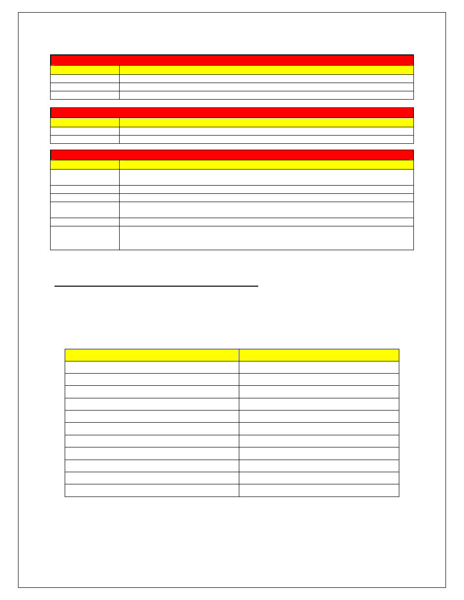
Plot One
Parameter
Description
AFR
Current measured AFR (Gasoline)
AFR Upper Limit
Current upper AFR limit value as set from the Wideband Failsafe Configuration tab
AFR Lower Limit
Current lower AFR limit value as set from the Wideband Failsafe Configuration tab
Plot Two
Parameter
Description
Manifold Pressure
Current measured Manifold Pressure in PSIg
Engine Speed
Current measured RPM, if connected and used
AEM EMS Series 1 / Series 2 Parameters
Below is the Wideband Failsafe related parameter names found in the AEM EMS Series 1 & 2
programmable ECU software when using the AEMNet daisy-chain. Note the slight difference in
nomenclature used with the AEM Wideband Gauge. Use the descriptions listed above for detailed
information.
AEM Wideband Failsafe Gauge Name
AEM EMS Series 1/Series 2 Name
AFR [AFR Gasoline]
WBFS AFR
AFR Upper Limit [AFR Gasoline]
WBFS Up Limit
AFR Lower Limit [AFR Gasoline]
WBFS Low Limit
Manifold Pressure [psi]
WBFS Boost
Engine Speed [rpm]
WBFS RPM
Alarm Status
WBFS Alarm
Alarm Reset Limit [ms]
WBFS Alarm Rst Lmt
Alarm Reset Counter [ms]
WBFS Alarm Rst Cnt
Alarm Delay Limit [ms]
WBFS Alarm Dly Lmt
Alarm Delay Counter [ms]
WBFS Alarm Dly Cnt
Alarm Status
WBFS Status
Plot Three
Parameter
Description
Alarm Source
Indicates what triggered the alarm condition; 3-low AFR condition, 5-high AFR condition, 3-
auxiliary input, 9-alarm test
Alarm Status
Indicates state of alarm; 1-alarm triggered, 0-alarm not triggered
Alarm Reset Limit
Alarm Reset value
Alarm Reset
Counter
Counts up from zero to Alarm Reset value once AFR has returned into the acceptable range
Alarm Delay Limit
Alarm Delay value
Alarm Delay
Counter
Counts up from zero to Alarm Delay value when AFR occurs outside the high or low AFR
limits; once full Alarm Delay value is reached the alarm will trigger; counter will reset back to
zero if AFR returns back into the acceptable range once count up has began