Installation – AEM 30-4900 Wideband Failsafe Gauge User Manual
Page 4
Page 5
Installation
1. Disconnect the negative battery cable.
2. Temporarily install gauge without bracket into desired mounting location. Gauge mounts into a 2-1/16”
(52MM) hole. The supplied rubber band can be used as a spacer around the gauge if it fits loosely in
mounting hole.
3. Locate a suitable place in the exhaust system to install the included oxygen sensor weld bung. On non-
turbocharged engines, mount the oxygen sensor in the exhaust system at least 18 inches downstream
from the exhaust port. On turbocharged engines the oxygen sensor must be installed after the
turbocharger, ideally 18” downstream from the turbocharger exhaust housing. NOTE: If the sensor is
mounted before the turbocharger the pressure differential will affect the accuracy of the unit. For
accurate readings, the sensor must be mounted upstream of the catalytic converters and/or auxiliary air
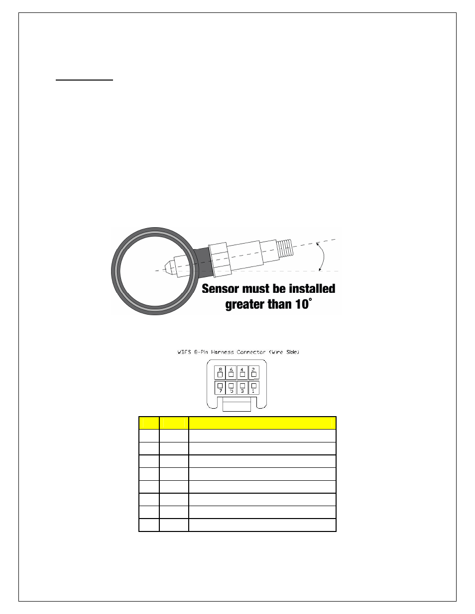
pumps. To prevent collection of liquids between the sensor housing and sensor element during the cold
start phase, the installation angle should be inclined at least 10° from horizontal with the electrical
connection upwards, see image below.
4. Next, the UEGO sensor 8-pin wiring harness should be routed to the oxygen sensor bung.
Pin Color
Description
1
N/C
N/C
2
White
Heat -
3
Orange
VM
4
Green
IA
5
Red
IP
6
Black
UN
7
N/C
N/C
8
Brown
12V