4 local operation via front panel, Local operation via front panel – BNC 835 User Manual User Manual
Page 34
Berkeley Nucleonics Corporation 2955 Kerner Blvd., San Rafael, CA 94901
Phone: 415-453-9955, Fax: 415-453-9956, Email: [email protected], Web: www.berkeleynucleonics.com
4 Local Operation via Front Panel
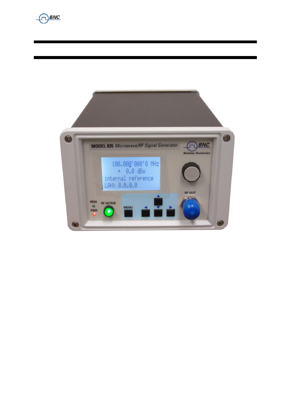
Most of the signal generator models offer direct front panel control.
A rotary knob and five keys (MENU, and four arrow keys) allow full control over the instrument.
shows the front panel of the MODEL 845.
Figure 4-a MODEL 845 Front Panel
RF On/Off button
The ON/OFF key toggles between RF output on and RF output off. The green light
is indicating whether the RF output is enabled (light on) or not.
RF 50
Ω connector
This female N- type connector provides the output for RF signals. The impedance
is 50 ohm. The damage level is +30 dBm maximum. The maximum allowed DC level is +/- 10 V.
Rotary knob
is used to switch between menus and to continuously change values at cursor position.
Menu Key
This is a multifunction key. The key is used to enter and exit menus. Press once to return
to CW menu, press multiple times to toggle between the currently selected submenu and the CW
menu.
↓ ↑ → ← Keys
These keys are used to move cursor within the screen menus. Within menus, the
→ ←
keys are also used to enter (
→
) and exit (
←
) in next menu hierarchy.
LAN LED
illuminates as soon a remote connection is active.