4 setting the gpib address, 3 perform firmware upgrade, 4 using toolbars – BNC 835 User Manual User Manual
Page 17: 5 basic cw operation (cw tab), Setting the gpib address, Erform, Irmware, Pgrade, Sing, Oolbars
Berkeley Nucleonics Corporation 2955 Kerner Blvd., San Rafael, CA 94901
Phone: 415-453-9955, Fax: 415-453-9956, Email: [email protected], Web: www.berkeleynucleonics.com
3.2.4
Setting the GPIB Address
If the instrument has the GPIB option installed, the GPIB address can be changed in the GPIB
submenu in the control tab. Valid GPIB address is 1 to 30.
To verify GPIB functionality, use the VISA Assistant available with the Agilent IO Library or the Getting
Started Wizard available with the National Instrument IO Library. These utility programs enable you to
communicate with the signal generator and verify its operation over GPIB. For information and
instructions on running these programs refer to the Help menu available in each utility.
3.3 Perform Firmware Upgrade
A firmware upgrade of the instrument can be done directly via the GUI. First make sure you are
connected to the right instrument and have the correct firmware binary file (.rar) ready. Then apply
Controller
Update Firmware and select the appropriate binary file that you have received from
Berkeley Nucleonics or downloaded from the Berkeley Nucleonics website. The update will take a few
seconds and after completion your instrument will reboot. Reconnect to the instruments after booting
is completed and continue with the updated firmware.
NOTE: Do not disconnect and power off
device during firmware update is in process.
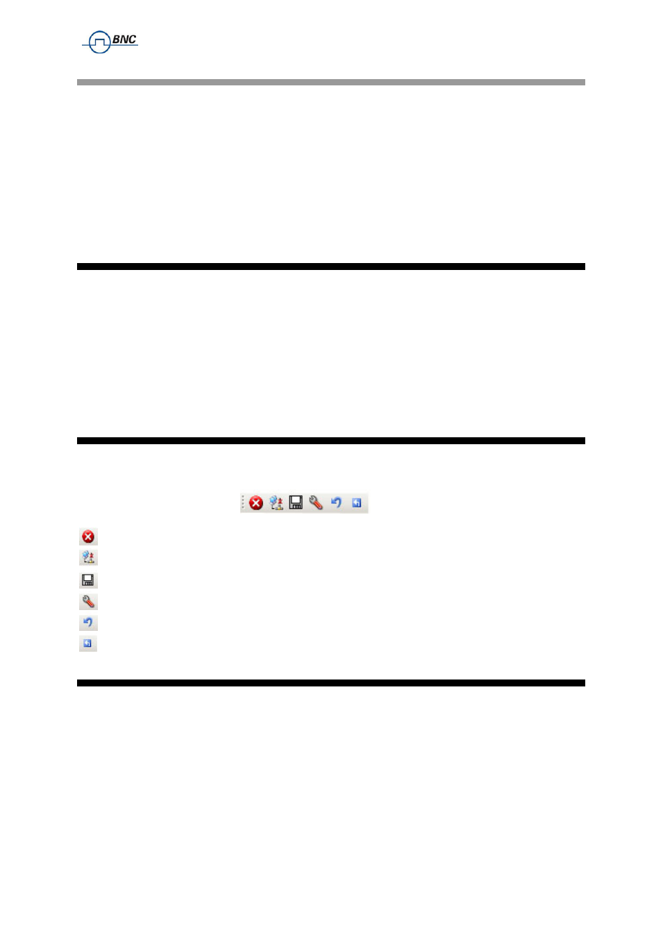
3.4 Using Toolbars
In the existing GUI Version there are two Toolbars available.
The standard toolbar looks like:
with the following symbol functionality:
Close the Application
Connect / Disconnect
Save to Memory
Network Configuration
Reset System
Restart Controller
3.5 Basic CW Operation (CW tab)
Berkeley Nucleonics signal generators are laboratory instruments designed to generate a synthesized
CW signal with good spectral purity and fixed or variable amplitude. To set a desired frequency,
relative phase and amplitude, click to the CW tab (
). The desired frequency, phase and
power can be set by clicking on the up and down arrows above and below each digit. The frequency is
settable in steps of 0.001 Hz, the phase is settable in steps of 0.1 degrees and the power in steps of
0.01 dB.
The RF ON/OFF button turns the RF power on and off. The green LED in the RF ON button indicates
that the RF output is enabled. The MOD ON/OFF button allows instant enabling (disabling) of a
previously enabled