Operating control description – Hale HP Series User Manual
Page 14
HP SERIES
PORTABLE PUMPS
USER OPERATION AND MAINTENANCE
14
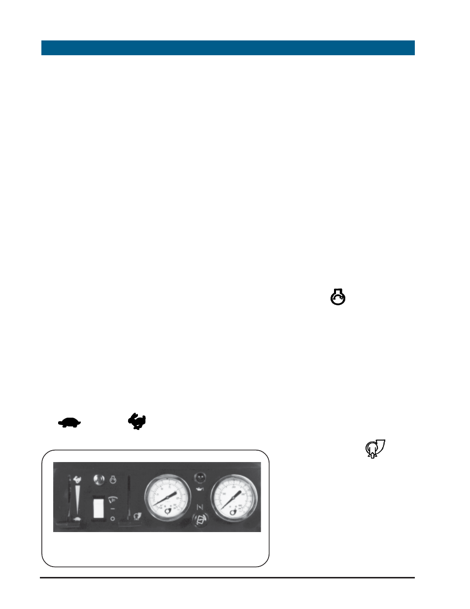
Most of the controls and indicators
necessary for the operation of the pump
are located on the operator panel.
The pump operator should become
thoroughly familiar with the location and
function of all pump controls and
indicators before attempting operation
of the pump.
The "I" version uses engine mounted
controls that are explained in the
enclosed Briggs and Stratton engine
manual.
The controls and indicators along with
their functions are as follows:
1. THROTTLE LEVER: The throttle lever
is located on the left side of the
instrument panel and controls the
speed at which the pump operates
to obtain the required flow. The lever
is a slide type "T"-handle that is
infinitely adjustable from SLOW
(
) to FAST (
).
2. MASTER SWITCH: The Master
switch is located below the start
button and is used to close the
electrical circuits on the pump to
enable operation. This is a rocker
type switch which when the (❍
❍
❍
❍
❍) side
is depressed energizes the electrical
system to enable pump operation.
When the (—)side is depressed the
electrical system is disconnected and
the pump stops.
3. START BUTTON (
): The start
button is located to the right of the
throttle lever and is used to start the
engine. Depressing the button after
the master switch is placed in the on
(—) position will engage the electric
starter on the pump engine. After
the button is released the button will
return to the normal position to
disengage the starter.
4. PRIMING LEVER (
): The
Priming Lever is a "T" type
handle located to the right of
the start switch and master
switch and is used to engage
the exhaust primer when the
pump is started. Pulling the "T"
handle down will engage the
primer. Due to spring force
3
OPERATING PANEL
OPERATING CONTROL DESCRIPTION