Figure 8-4: sample cafspro display readouts -2, 3 water flow sensor calibration – Hale CAFSPro User Manual
Page 64
❑ Calibration
64
CAFSPro User Operation Manual
p/n: 029-0020-75-0
6.
The display shows CAL for several seconds, followed by P25.0. The
FLOW (
) LED also lights (Airflow PWM Value). (See Figure 8-3:
‘Sample CAFSPro Display Readouts -1’ on page 63.)
7.
On the CAFSPro display, press the DISPLAY (
i
) pad three (3) times until
the RATIO LED lights (
) and the display shows Fxx.x (water flow
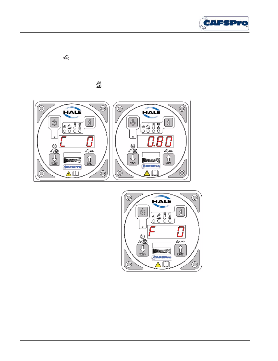
value). (See Figure 8-4: ‘Sample CAFSPro Display Readouts -2.’)
Figure 8-4: Sample CAFSPro Display Readouts -2
8. Press the DISPLAY (
i
) pad to show
the air flow calibration factor. The
default value is 0.80. (See Figure
8-4: ‘Sample CAFSPro Display
Readouts -2.’)
Note: If a value other than 0.80 is
shown, consult the factory.
9. Proceed with “Water flow sensor
calibration.”
8.3
WATER FLOW SENSOR CALIBRATION
Notes: The flow sensor is calibrated at Hale Products Inc. and matched to the
control unit. If the system is installed properly only minor adjustments should be
necessary to the flow sensor reading. Flow sensor calibration should be verified
during NFPA/UL testing of the apparatus and delivery to end user.
An accurate flow measuring device must be used to measure the water flow when
calibrating the flow sensor. Use a suitable size, smooth bore nozzle and an accu-
rate Pitot Gauge instrument.