Qpak, qflo and qflo-plus pumps, Impeller – Hale Q Series Muscle User Manual
Page 27
27
MUSCLE (Midship) Pumps Installation, Operation, and Maintenance Manual
p/n: 029-0020-63-0
Introduction
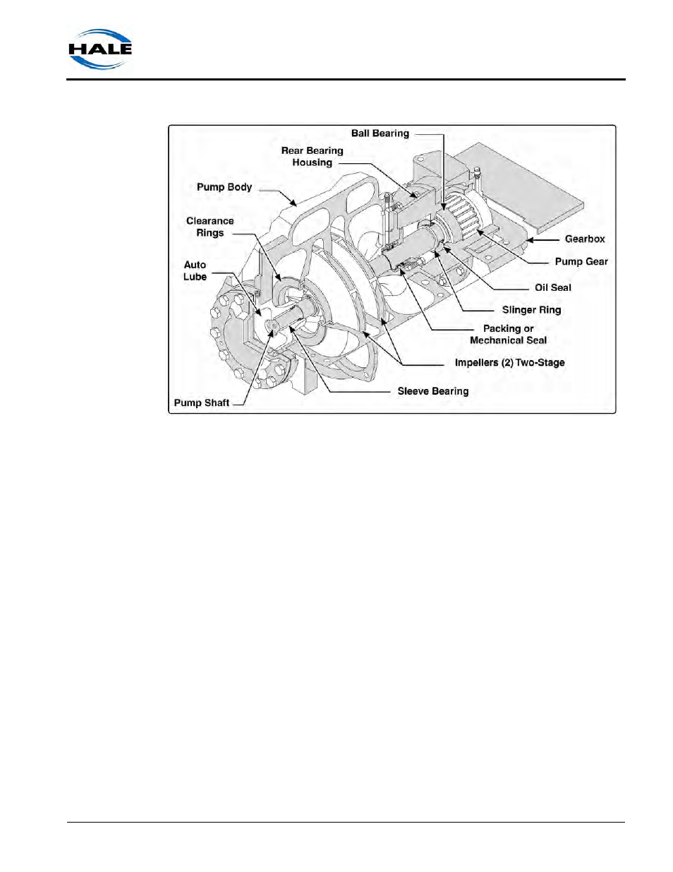
Figure 2-7: Typical Midship Two-Stage Centrifugal Pump
Qpak, Qflo and Qflo-Plus Pumps
The pump bodies are a single piece construction. To avoid disturbing discharge or
suction piping, the gearbox and rear pump head / bearing housing must be removed
to service the impeller, clearance rings and mechanical seal.
The pumps include two large suction inlets on the left and right sides. The incoming
water is directed to the impeller through the suction passages.
A tank suction valve opening, located on the rear of the pump, allows for high flows
from the booster tank. An optional built-in check valve is available to prevent tank
over-pressurization.
Discharge valves in the basic pump configuration are mounted at either side of the
pump body. However, the manifolded pump body provides several additional dis-
charge locations (facing front, back, or up) to accommodate additional discharge
valves.
Impeller
The impeller provides velocity to the water. Water enters the rotating impeller at the
intake (or eye), and is confined by the shrouds and the vanes to build pressure. (See
Figure 2-8: “Impeller Operation” on page 28.)