4 removing the pump assembly, Figure 7-1: typical muscle (midship) pump overview – Hale Q Series Muscle User Manual
Page 108
Repair and Corrective Maintenance
108
MUSCLE (Midship) Pumps Installation, Operation, and Maintenance Manual
p/n: 029-0020-63-0
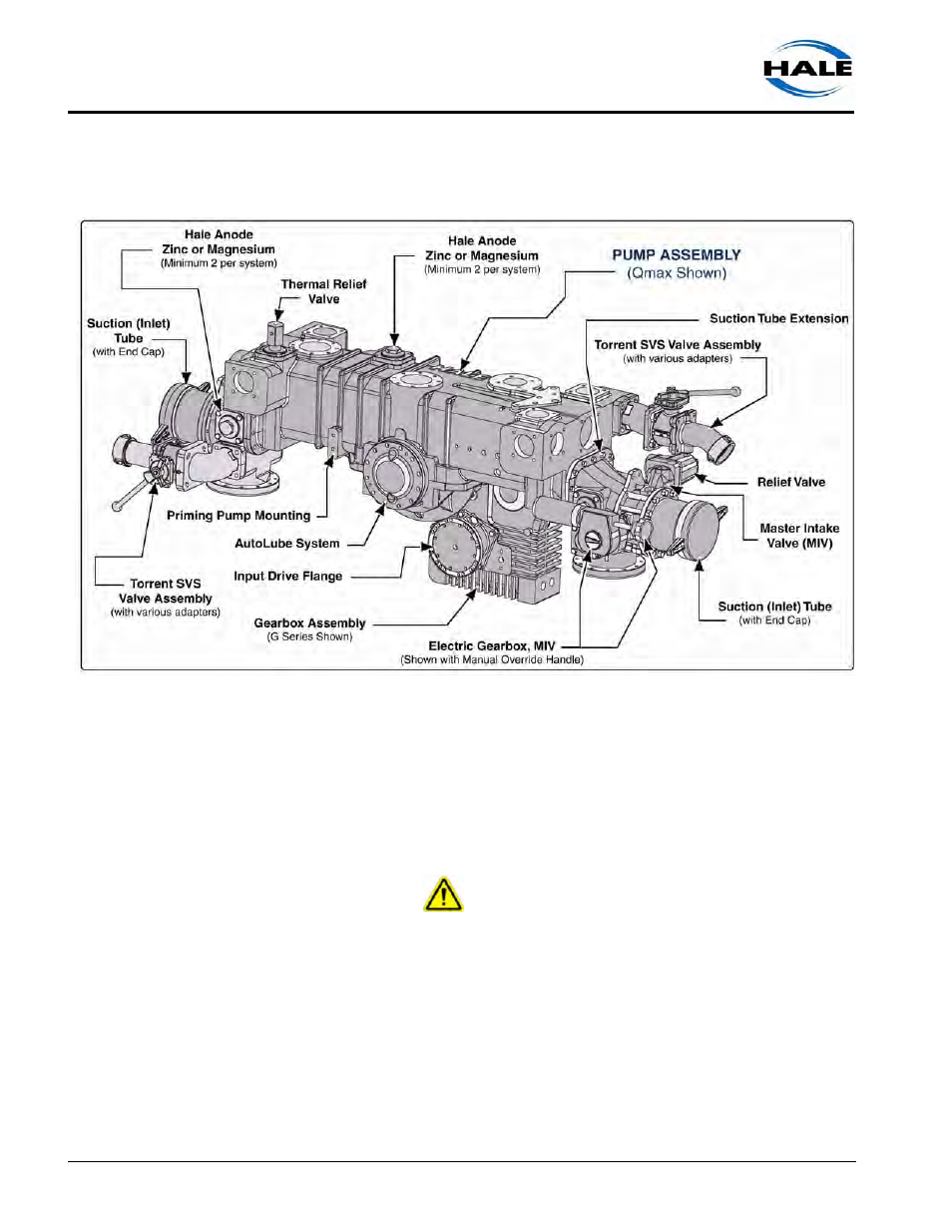
7.4 REMOVING THE PUMP ASSEMBLY
Figure 7-1: Typical Muscle (Midship) Pump Overview
1.
First, review preceding Section “Before You Begin...” on page 103.
See Section “Drawing Package” on page 203. and review the appropriate Instal-
lation Drawing.
2.
Install 5/8”-11 UNC eyebolts into the lifting holes on the midship pump body. (See
Figure 7-2: “Lifting Eyebolt Attachment Layout,” on page 109.)
CAUTION!
ALWAYS USE PROPER LIFTING AND SUPPORT APPARATUS (JACKS, HOISTS,
STRAPS, ETC.) WHEN SERVICING THE UNIT. EXERCISE CARE WHEN USING CHAINS
TO PROTECT FINISHED SURFACES FROM SCRATCHES. ALSO SEE WARNINGS!
NOTE ON PAGE 104.
3.
With the pump assembly properly supported and balanced, disconnect the
mounting brackets that secure the assembly to the apparatus chassis frame.