Figure 9-5: typical j series gearbox assembly – Hale Q Series Muscle User Manual
Page 158
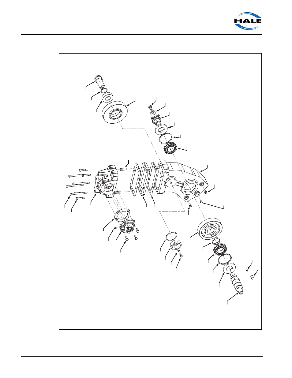
Gearbox Maintenance
158
MUSCLE (Midship) Pumps Installation, Operation, and Maintenance Manual
p/n: 029-0020-63-0
Figure 9-5: Typical J Series Gearbox Assembly
Idler Shaft
O-Ring
Idler Gear
(57 T
eeth)
He
x Head Capscre
w
(5/8”
-11 UNC x 1-1/2”)
W
asher
Flang
e
Lo
wer Gearbo
x Housing
Vie
w Gaug
e
(1/2”
NPT)
Ma
gnetic Plug
(1/2”
NPT)
Plug
(1/2”
NPT)
Scre
w A (4)
Scre
w B (4)
Upper Housing
Gasket
Breather V
ent
End Cap
He
x Head Capscre
w
(1/2”
-13 UNC x 1-1/4”)
Do
wel Pin (2)
Gear Spacer
Spacer Gasket (2)
Retaining Ring
T
apered Roller Bearing
W
asher
He
x Head Capscre
w
(1/2”
-13 UNC x 2”)
Drive Gear
(54 T
eeth)
Spacer
Spherical Bearing
Retaining Ring
Oil Seal
Input Shaft
Key
Input Gear K
e
y
Spherical Bearing
Retaining Ring
Oil Seal
T
apered Roller Bearing
This manual is related to the following products: