Bryant 313AAV User Manual
Page 23
23
A03221
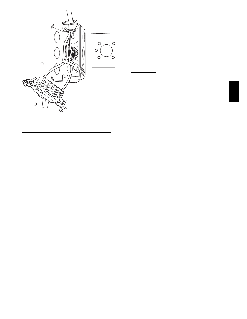
Fig. 23 -- Field--Supplied Electrical Box on Furnace Casing
POWER CORD INSTALLATION IN FURNACE J--BOX
NOTE: Power cords must be able to handle the electrical
requirements listed in Table 7. Refer to power cord
manufacturer’s listings.
1. Remove cover from J--Box.
2. Route listed power cord through 7/8--in. (22 mm) diameter
hole in J--Box.
3. Secure power cord to J--Box bracket with a strain relief
bushing or a connector approved for the type of cord used.
4. Secure field ground wire to green ground screw on J--Box
bracket.
5. Connect line voltage leads as shown in Fig. 25.
6. Reinstall cover to J--Box. Do not pinch wires between
cover and bracket.
BX CABLE INSTALLATION IN FURNACE J--BOX
1. Remove cover from J--Box.
2. Route BX cable into 7/8--inch diameter hole in J--Box.
3. Secure BX cable to J--Box bracket with connectors
approved for the type of cable used.
4. Secure field ground wire to green ground screw on J--Box
bracket.
5. Connect line voltage leads as shown in Fig. 25.
6. Reinstall cover to J--Box. Do not pinch wires between
cover and bracket.
24--V WIRING
Make field 24--v connections at the 24--v terminal strip. (See Fig.
23.) Connect terminal Y/Y2 as shown in Fig. 24 for proper
cooling operation. Use only AWG No. 18, color--coded, copper
thermostat wire.
The 24--v circuit contains an automotive--type, 3--amp.. fuse
located on the control. Any direct shorts during installation,
service, or maintenance could cause this fuse to blow. If fuse
replacement is required, use ONLY a 3--amp.. fuse of identical
size.
ACCESSORIES
1. Electronic Air Cleaner (EAC)
Connect an accessory Electronic Air Cleaner (if used)
using 1/4--in female quick connect terminals to the two
male 1/4--in quick--connect terminals on the control board
marked EAC--1 and EAC--2. The terminals are rated for
115 VAC, 1.0 amps maximum and are energized during
blower motor operation. (See Fig. 24.)
2. Humidifier (HUM)
Connect an accessory 24 VAC, 0.5 amp. maximum
humidifier (if used) to the 1/4--in male quick--connect
HUM terminal and COM--24V screw terminal on the
control board thermostat strip. The HUM terminal is
energized when gas valve relay (GVR) is energized. (See
Fig. 24.)
NOTE: A field--supplied, 115--v controlled relay connected to
EAC terminals may be added if humidifier operation is desired
during blower operation.
NOTE: DO NOT connect furnace control HUM terminal to
HUM (humidifier) terminal on Thermidistatt, Zone Controller
or similar device. See Thermidistat, Zone Controller, thermostat,
or controller manufacturer’s instructions for proper connection.
VENTING
The furnace shall be connected to a listed factory built chimney
or vent, or a clay--tile lined masonry or concrete chimney. Venting
into an unlined masonry chimney or concrete chimney is
prohibited.
When an existing Category I furnace is removed or replaced, the
original venting system may no longer be sized to properly vent
the attached appliances. An improperly sized Category I venting
system could cause the formation of condensate in the furnace
and vent, leakage of condensate and combustion products, and
spillage of combustion products into the living space.
313A