Connection diagram, Before connecting the amplifier, 03 connecting the units – Pioneer GM-6500F User Manual
Page 6
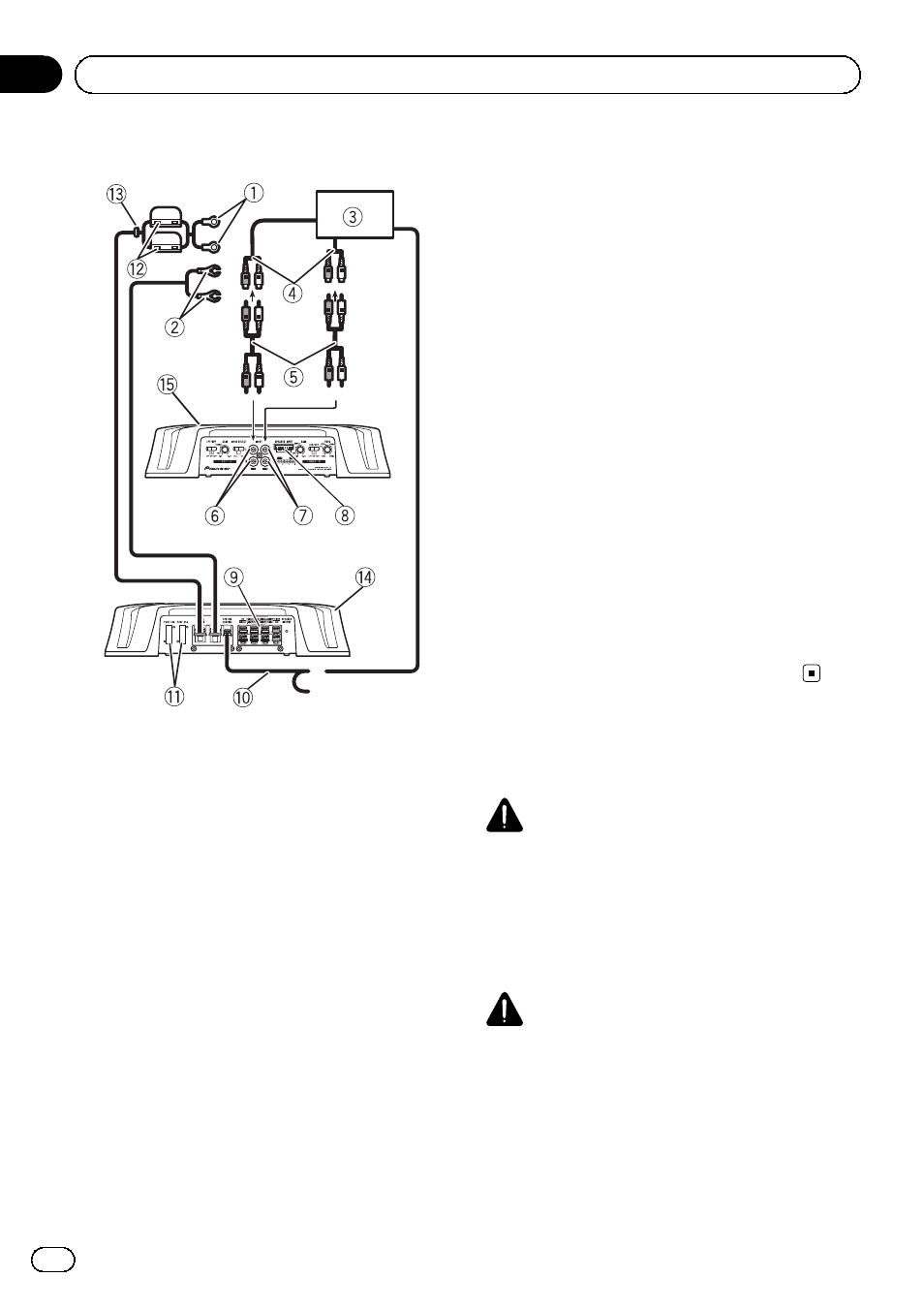
Connection diagram
1 Special red battery wire
RD-223 (sold separately)
After completing all other amplifier connec-
tions, finally connect the battery wire terminal
of the amplifier to the positive (
+) battery
terminal.
2 Ground wire (Black)
RD-223 (sold separately)
Connect to metal body or chassis.
3 Car stereo with RCA output jacks (sold sepa-
rately)
4 External output
If only one input plug is used, do not connect
anything to RCA input jack B.
5 Connecting wire with RCA pin plugs (sold se-
parately)
6 RCA input jack A
7 RCA input jack B
8 Speaker input terminal (use a connector in-
cluded)
Please see the following section for speaker
connection instructions. Refer to Connections
when using the speaker input wire on page 9.
9 Speaker output terminals
Please see the following section for speaker
connection instructions. Refer to Connections
when using the speaker input wire on page 9.
a System remote control wire (sold separately)
Connect male terminal of this wire to the sys-
tem remote control terminal of the car stereo.
The female terminal can be connected to the
auto-antenna relay control terminal. If the car
stereo lacks a system remote control terminal,
connect the male terminal to the power term-
inal via the ignition switch.
b Fuse (25 A) × 2
c Fuse (30 A) × 2
d Grommet
e Rear side
f Front side
Note
INPUT SELECT (input select) switch must be set.
For details, see Setting the unit on page 4.
Before connecting the
amplifier
WARNING
! Secure the wiring with cable clamps or adhe-
sive tape. To protect the wiring, wrap sections
in contact with metal parts in adhesive tape.
! Never cut the insulation of the power supply
to feed power to other equipment. Current ca-
pacity of the wire is limited.
CAUTION
! Never shorten any wires, the protection circuit
may malfunction.
! Never ground speaker wire directly or band to-
gether multiple speakers
’ negative (*) lead
wires.
En
6
Section
03
Connecting the units