Function fittings and flow controls – Norgren Flow Controls User Manual
Page 24
FIT-3-24
Littleton, CO USA
Phone 303-794-2611
www.norgren.com
Function Fittings and Flow Controls
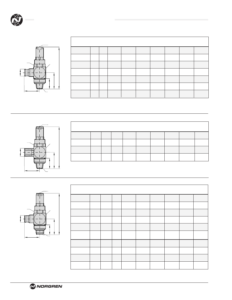
Dimensions in Inches (mm)
C
A
H
E
B
G
I
D
2
1
J
O.D. Tube
Pressure Reducing Fitting - 124GB
A
B
Part
O/D
NPT
D
E
H SQ
J
Number
Tube Thread
C
(max)
A/F
G
A/F
I
A/F
12 4GB 0218 5⁄32
1⁄8
0.89
2.87
0.67
–
0.63
0.78
0.20
(23)
(73)
(17)
(16)
(20)
(5)
12 4GB 0418
1⁄4 1⁄8
0.91
2.87
0.67
–
0.63
0.78
0.20
(23)
(73)
(17)
(16)
(20)
(5)
12 4GB 0428
1⁄4
1⁄4
1.0 3.10 0.67 0.64
0.79 1.02 0.20
(25)
(79)
(17)
(16)
(20)
(26)
(5)
12 4GB 0528 5⁄16
1⁄4
1.03 3.10 0.67 0.64
0.79 1.02 0.20
(26)
(79)
(17)
(16)
(20)
(26)
(5)
12 4GB 0538 5⁄16
3⁄8
1.11 3.35 0.87 0.69
0.94 1.14 0.34
(28)
(85)
(22)
(18)
(24)
(29)
(6)
12 4GB 0638
3⁄8
3⁄8
1.29 3.35 0.87 0.69
0.94 1.14 0.34
(33)
(85)
(22)
(18)
(24)
(29)
(6)
12 4GB 0748
1⁄2 1⁄2
1.56
3.54
1.06
–
1.18
1.38
0.24
(40)
(90)
(27)
(30)
(35)
(6)
1) Inlet Port
2) Outlet Port
Note: For mounting in ports 2 & 4 of a pneumatic directional control valve
C
A
H
E
B
G
I
D
2
1
J
Pressure Reducing Fitting - 124GB
A
B
Part
NPT
NPT
D
E
H SQ
J
Number
Thread Thread
C
(max)
A/F
G
A/F
I
A/F
12 4GB 1818
1⁄8 1⁄8
0.83
2.87
0.67
–
0.64
0.78
0.20
(21)
(73)
(17)
(16)
(20)
(5)
12 4GB 2828
1⁄4
1⁄4
1.14
3.10 0.67 0.64 0.79 1.02 0.20
(29)
(79)
(17)
(16)
(20)
(26)
(5)
12 4GB 3838
3⁄8
3⁄8
1.20
3.35 0.87
0.69 0.94 1.14 0.24
(31)
(85)
(22)
(18)
(24)
(29)
(6)
12 4GB 4848
1⁄2
1⁄2
1.54
3.54
1.06
–
1.18
0.98
0.24
(39)
(90)
(27)
(30)
(35)
(6)
1) Inlet Port
2) Outlet Port
Note: For mounting in ports 2 & 4 of a pneumatic directional control valve
C
A
H
E
B
G
I
D
2
1
J
Pressure Reducing Fitting - 102GB
A
B
Part
O/D
ISO G
D
E
H SQ
J
Number
tube
Thread
C
(max)
A/F
G
A/F
I
A/F
10 2GB 0418
4
1⁄8
0.89
2.87
0.67
0.25
0.64
0.78
0.20
(22)
(73)
(17)
(6)
(16)
(20)
(5)
10 2GB 0628
6
1⁄4
1.00
3.54 0.67 0.41 0.79 1.02 0.20
(25)
(90)
(17)
(11)
(20)
(26)
(5)
10 2GB 0828
8
1⁄4
1.03
3.54 0.67 0.41 0.79 1.02 0.20
(26)
(90)
(17)
(11)
(20)
(26)
(5)
10 2GB 0838
8
3⁄8
1.11
3.78 0.87 0.43 0.94 1.14 0.24
(28)
(96)
(22)
(11)
(24)
(29)
(6)
10 2GB 1038
10
3⁄8
1.29
3.78 0.87 0.43 0.94 1.14 0.24
(33)
(96)
(22)
(11)
(24)
(29)
(6)
A
B
Part
ISO G
ISO G
D
E
H SQ
J
Number
Thread Thread
C
(max)
A/F
G
A/F
I
A/F
10 2GB 1818
1⁄8
1⁄8
0.69
2.87
0.67
0.25
0.64
0.78
0.20
(18)
(73)
(17)
(6)
(16)
(20)
(5)
10 2GB 2828
1⁄4
1⁄4
0.96
3.19
0.37
0.41
0.79
1.02
0.20
(25)
(81)
(17)
(11)
(20)
(26)
(5)
10 2GB 3838
3⁄8
3⁄8
1.06
3.46
0.87
0.43
0.94
1.14
0.24
(27)
(88)
(22)
(11)
(24)
(29)
(6)
10 2GB 4848
1⁄2
1⁄2
1.34
3.50
1.06
0.37
1.18
1.42
0.24
(34)
(89)
(27)
(10)
(30)
(36)
(6)
1) Inlet Port
2) Outlet Port
Note: For mounting in ports 2 & 4 of a pneumatic directional control valve