Function fittings and flow controls – Norgren Flow Controls User Manual
Page 11
Littleton, CO USA
Phone 303-794-2611
www.norgren.com
FIT-3-11
Function Fittings and Flow Controls
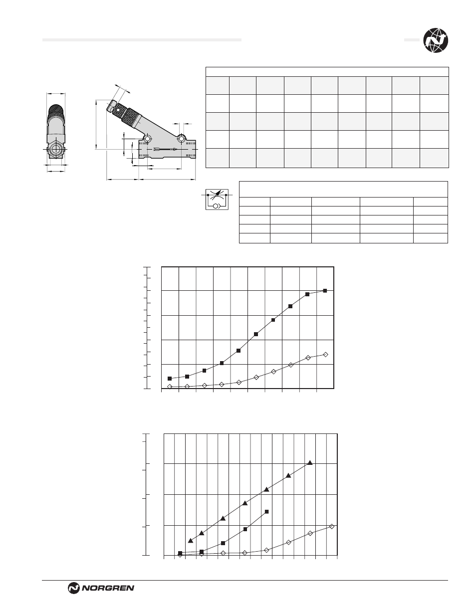
Dimensions in Inches (mm)
Flow Control
ØA
1.06 (27)
A/F
1.10 (28)
C
L
A
.52
(13)
B
1
2
.63
(16)
.67
(17)
M (max)
.51 (13)
ØA
Typical Model Number:
C/839
1⁄2 NPT
M/839
G1⁄2
Type: Uni-directional
Free flow is from ‘2’ to ‘1’, indicated by arrow
Model
Max. Regulating Max. Free
Port
NPT
ISO G
Flow Cv
Flow Cv
1/8
C/836
S/836
0.17
0.6
1/4
C/837
M/837
0.49
1.0
1/2
C/839
M/839
2.6
3.6
3/4
C/840
M/840
3.7
6.5
1
C/855
M/855
8.4
8.9
Thread
NPT
G
A
L
C
B
M (max)
D
1/8
C/836
S/836
.96
1.81
1.06
.33
3.11
.67
(25)
(46)
(27)
(8)
(79)
(17)
1/4
C/837
M/837
1.63
2.36
.98
.20
1.46
.87
(42)
(60)
(25)
(5)
(37)
(22)
1/2
C/839
M/839
2.25
3.7
2.09
.33
3.11
1.10
(57)
(94)
(53)
(8)
(79)
(28)
3/4
C/840
M/840
2.99
4.69
2.60
.34
4.09
1.38
(76)
(119)
(66)
(9)
(104)
(35)
1
C/855
M/855
3.54
5.90
4.22
.51
5.79
2.04
(90)
(150)
(107)
(13)
(147)
(52)
1
2
1
3
5
7
9
C/837
17.07 scfm
(6-5 bar)
C/836
5.95 scfm
(6-5 bar)
FLOW CHARACTERISTICS
FLOW
NUMBER OF TURNS
0
2
4
0
8
12
16
20
4
6
8
10
dm
3
/s
scfm
1
3
5
7
9
11
13
15
0
0
100
200
300
400
50
100
150
200
dm
3
/s
scfm
C/855
324.36 scfm
(6-5 bar)
C/840
152.64 scfm
(6-5 bar)
C/839
101.97 scfm
(6-5 bar)
FLOW CHARACTERISTICS
NUMBER OF TURNS
FLOW