Function fittings and flow controls, Guidelines for typical installation – Norgren Flow Controls User Manual
Page 20
FIT-3-20
Littleton, CO USA
Phone 303-794-2611
www.norgren.com
Function Fittings and Flow Controls
Guidelines for Typical Installation
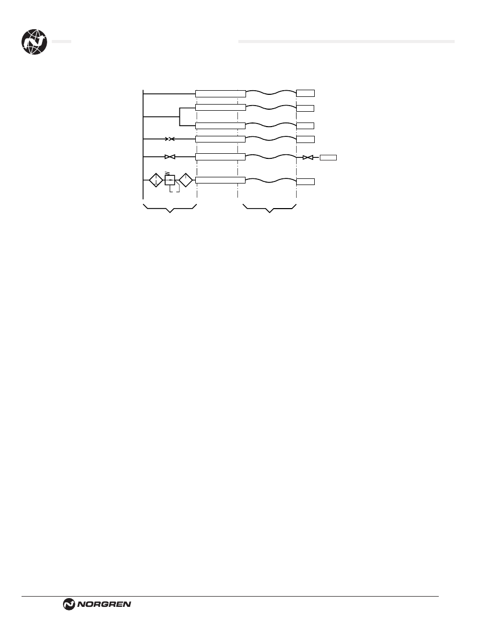
The air fuse should be installed directly between fixed or rigid pipework and the flexible tube to protect the whole
length of the flexible tube. Only tubing after the air fuse is protected. The air fuse must be installed in the correct
orientation. Failure to do this will render it ineffective. When a shut off valve is located before the air fuse, the
valve must be opened slowly in order to control initial air flow and avoid decompression effects which may trip the
air fuse.
It should be noted that the OSHA standard (29 CFR ChXVII Para 1926.302-b7) relating to pneumatic power tools
states “All hoses exceeding 1/2" inside diameter shall have a safety device at the source of supply or branch
line to reduce pressure in the case of hose failure.”
Choosing an Air Fuse*
a) The port size of the air fuse should be nominally equal to that of the supply lines - e.g. a 1⁄2 (12.7 mm) air fuse
should be used with a 1⁄2'' (12.7mm) ID hose.
b) Always select the high flow model (91) if there is sufficient system pressure for the length of hose to be
protected. See tables hose length vs. minimum supply pressure.
c) If there is insufficient system pressure, or long hose lengths are to be protected, use model 90.
d) After installation always test each valve for proper function. See section below on how to check an air fuse.
e) The pneumatic system must be capable of delivering the flow required to activate the air fuse. For this reason,
the air fuse is not suitable for use with the Norgren R07 miniature range in certain installations.
f) For use with spring coils consult table. See table flow vs. pressure supply.
Verifying Operation of an air fuse
●
Install the air fuse following the instructions supplied
●
Connect tool or complete circuit to the air line
●
Switch on operation to ensure a complete cycle is performed
●
If tool or complete circuit starts and runs satisfactorily, stop operation and drain air line. Disconnect hose from
tool or circuit and secure hose end. Turn on air supply progressively (to avoid decompression effect). Prior to
fully reaching operation conditions, the air fuse should suddenly activate and cut off the flow. A slight air flow
will remain as part of the automatic re-set function. If the air fuse is not activated the unit should be
disconnected and the lower flow range air fuse should be used.
* Consult factory for the availability of Excel™ based sizing program.
AIR SUPPLY
TOOL
TOOL
TOOL
TOOL
TOOL
TOOL
RIGID LINE
FLEXIBLE LINE
Air Fuse
Air Fuse
Air Fuse
Air Fuse
Air Fuse
Air Fuse