Val- 44, Valve manifolds vs26 series, Valves – Norgren VS26 Series Valve Manifolds User Manual
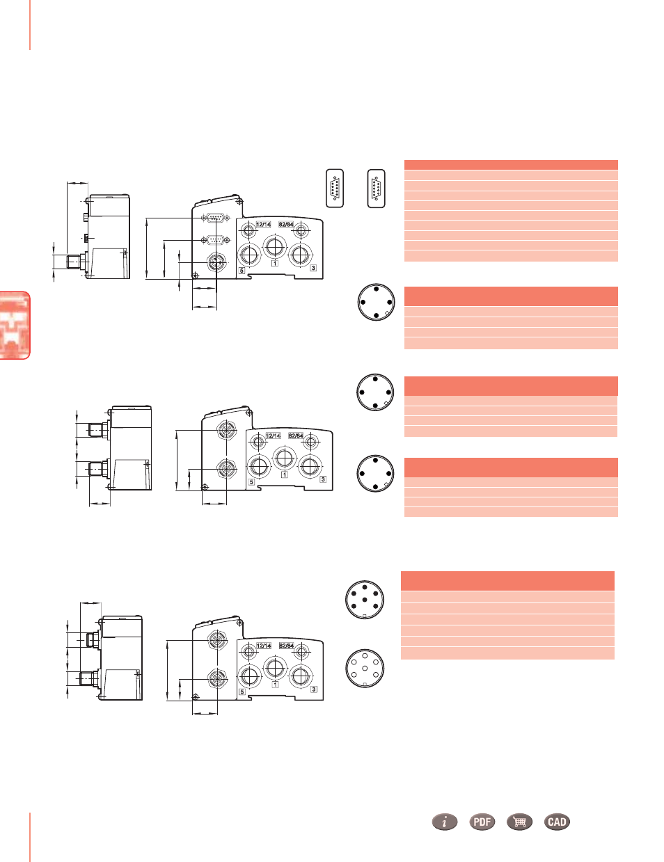
Page 19: Fieldbus protocol: as-interface, Fieldbus protocol: fd67 bus, Bus connector: m12 4-pin, Power connector: m12 4-pin, Bus connector: d-sub 9-pin, Bus connector: m12 6-pin
Valves
www.norgren.com/usa
VAL-
44
Valve Manifolds VS26 Series
Plug-in Mini ISO Valves
2x2/2, 2x3/2, 5/2 and 5/3 valves, ISO 15407-2, Size 26 mm
2.32
(59)
0.85
(21.5)
0.61
(15.5)
0.87
(22)
1.46
(37)
1.04
(26.5)
M 12
Connector: 1 x M12 / M12 4-pin
Fieldbus protocol: Interbus-S
2.32
(59)
0.73
(18.5)
0.60
(15)
0.85
(21.5)
M 12
M 12
3
2
4
1
3
2
4
1
Fieldbus protocol: AS-Interface
Connector: 2 x D-Sub 9-pin / M12 4-pin
Bus connector: M12 4-pin
1
AS-I 3)
2
-
-
3
AS-I -
4
-
-
1
+24 V DC
+/-10%
4)
2
-
-
-
3
0 volts
-
-
4
-
-
-
Power connector: M12 4-pin
2
3
4
6
7
8
9
1
5
2
3
4
6
7
8
9
1
5
1
2
3
4
1
2
3
4
1
2
3
4
Male
Male
Male
Male
Female
Communication in
Communication
in/out
Communication out
Bus connector: D-Sub 9-pin
1
DO
DO
2
DI
DI
3
OVI
OVI
4
–
–
5
–
+5VI
6
/DO
/DO
7
/DI
/DI
8
–
–
9
–
RBST
Pin no.
Function Male
Function Female
1
300 mA
2
1)
3
2)
4
-
Power connector: M12 4-pin
Pin no.
Function
Tolerance
Max.
current
Tolerance
Max.
current
Max.
current
Pin no.
Function
Pin no.
Function
24 VB logic circuit supply
+/-25%
24 VA valves
+/-10%
0 volts
–
Earth
–
1) I
max = 10 mA + n*60 mA
n = number of energized solenoids
2) I
max = IVA + IVB
3) Single slave: 40 mA
Double slave: 75 mA
4) Single slave:
Imax = 20 mA + n*60 mA
Double slave:
Imax = 35 mA + n*60 mA
n = number of energized solenoids
5)Imax = n*60 mA
n = number of energized solenoids
Bus connector: M12 6-pin
1
24 V actuator supply
±10%
5)
2
24 V sensor supply/internal supply ±25%
30 mA
3
Ground
-
-
4
Internal system connection
-
-
5
Internal system connection
-
-
6
Ground
-
-
2.32
(59)
0.73
(18.5)
0.59
(15)
0.85
(21.5)
M 12
M 12
3
2
4
1
3
2
4
1
Pin no.
Function
Tolerance
Max.
current
Connector: 2 x M12 6-pin (power connector integrated
in bus connectors)
Fieldbus protocol: FD67 bus
Female
Communication
out
4
6
3
5
2
1
Male
Communication
in
4
6
5
3
1
2