Fieldbus options, Overview, Fieldbus protocol: profibus dp – Norgren VS18 Series Valve Islands User Manual
Page 12: Bus connector: d-sub 9-pin, Power connector: m12 4-pin, Bus connector: m12 5-pin (b-coded), Power connector: 7/8 5-pin
3-045
FIELDBUS OPTIONS
: Overview
22
21,5
16
51
M 12
1
4
3
2
22,5
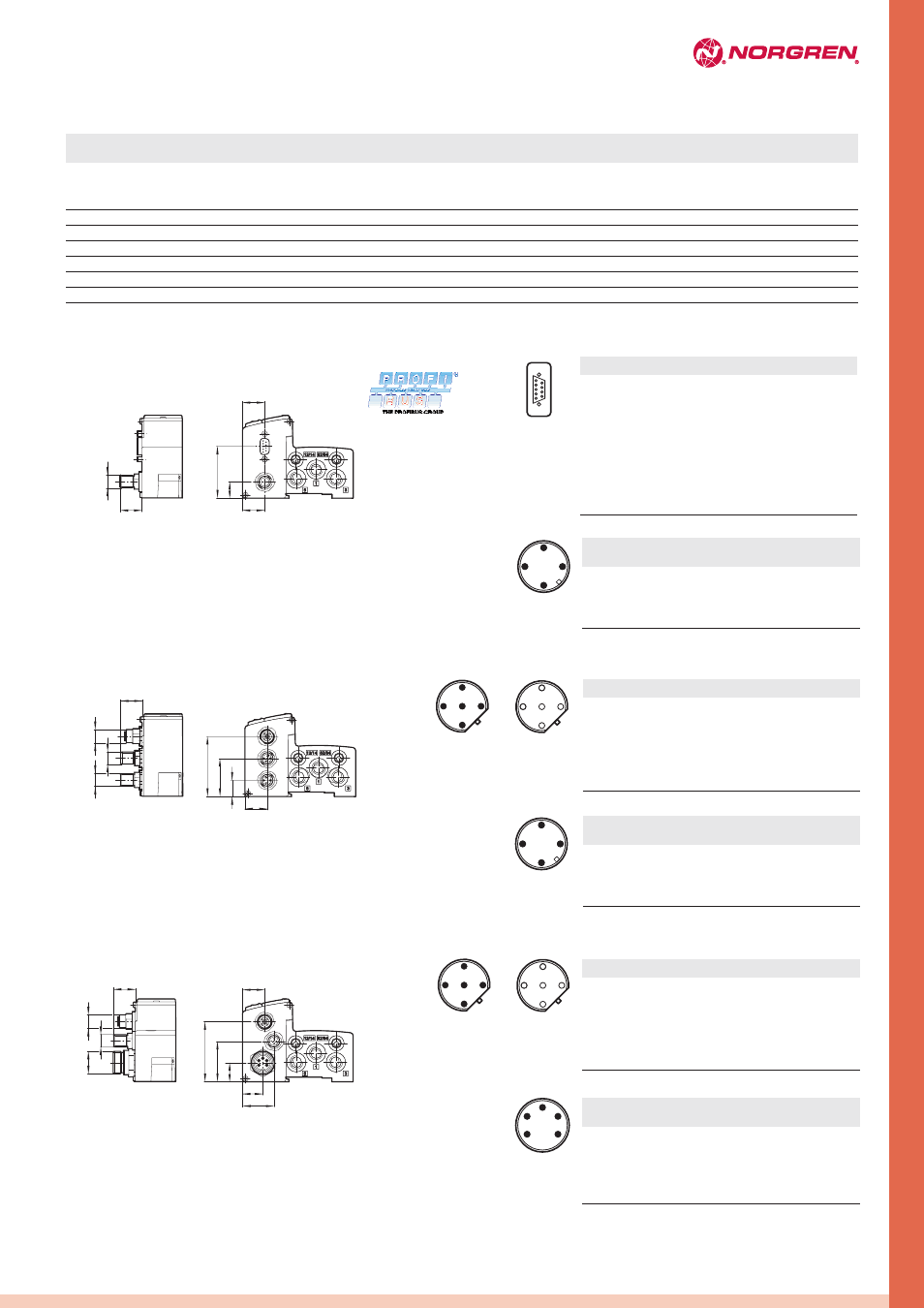
Fieldbus protocol: Profibus DP
Connector: 1 x D-Sub 9-pin / M12 4-pin
Bus connector: D-Sub 9-pin
1
Shield
2
N/C
3
B-line (red) RxD / TxD-P
4
N/C
5 DGND
(OVI)
isolated
6
VP (5VI) isolated
7
N/C
8
A-line (green) RxD / TxD-N
9
N/C
1
24 VB logic circuit supply
±25%
300 mA
2
24 VA valves
±10%
1)
3
0 V
–
2)
4
Earth
–
–
Power connector: M12 4-pin
1
2
3
4
2
3
4
6
7
8
9
1
5
Male
Female
Communication
in/out
Pin no.
Function
Pin no. Function
Max.
current
Connector: 2 x M12 5-pin / M12 4-pin
37,5
22
21,5
16
59
M12
M12
M12
Bus connector: M12 5-pin (B-coded)
1
24 VB logic circuit supply
±25%
300 mA
2
24 VA valves
±10%
1)
3
0 V
–
2)
4
Earth
–
–
Power connector: M12 4-pin
4
1
5
3
2
3
2
5
4
1
1
2
3
4
Male
Pin no.
Function
Pin no.
Function
Tolerance
Max.
current
41,5
18,5
21,5
18,5
60
M 12
M 12
1
4
3
2
16 UN
29,5
1
5
4
3
2
19
Bus connector: M12 5-pin (B-coded)
4
1
5
3
2
3
2
5
4
1
3
4
2
5
1
Male
Male
Female
Communication
in
Communication
out
Connector: 2 x M12 5-pin / 7/8 5-pin
1)
I
max
= 10 mA + n*60 mA
n = number of energized solenoids
2)
I
max
= I
VA
+ I
VB
Profibus DP
1 x D-Sub 9-pin
M12 4-pin
04/05/06/07/08/09/10/11/12/13/14/15/16
32
2 x M12 5-pin
M12 4-pin
04/05/06/07/08/09/10/11/12/13/14/15/16
32
2 x M12 5-pin
7/8 5-pin
04/05/06/07/08/09/10/11/12/13/14/15/16
32
Interbus-S
2 x D-Sub 9-pin
M12 4-pin
04/05/06/07/08/09/10/11/12/13/14/15/16
32
AS-Interface - Single slave
1 x M12 4-pin
M12 4-pin
02/03/04
4
AS-Interface - Double slave
1 x M12 4-pin
M12 4-pin
04/05/06/07/08
8
DeviceNet
1 x M12 5-pin
M12 4-pin
04/05/06/07/08/09/10/11/12/13/14/15/16
32
CANopen
1 x M12 5-pin
M12 4-pin
04/05/06/07/08/09/10/11/12/13/14/15/16
32
Murrelektronic Cube67
2 x M12 6-pin
(integrated in bus connector)
04/05/06/07/08/09/10/11/12/13/14/15/16
32
Power connector (Fieldbus &
valves)
Max. no.
solenoids
No. of stations
Fieldbus
interface/connector
Fieldbus protocol
1
5VI Opto isolated
2
A-line (green)
3
OVI Opto isolated
4
B-line (red)
5
Shield
Threaded joint
Shield
Pin no.
Function
1
5VI Opto isolated
2
A-line (green)
3
OVI Opto isolated
4
B-line (red)
5
Shield
Threaded joint
Shield
1
–
–
–
2
0 V
–
2)
3
Earth
–
–
4
24 VA valves
±10%
1)
5
24 VB logic circuit supply
±25%
300 mA
Pin no.
Function
Tolerance
Max.
current
Power connector: 7/8 5-pin
Tolerance
Communication
in
Communication
out
Male
Female