Digital filter, Filter followed by a sinc, Sin x x 3 – Cirrus Logic CS5534-BS User Manual
Page 38
CS5532/34-BS
38
DS755F3
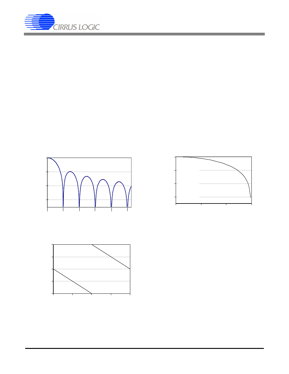
2.9. Digital Filter
The CS5532/34 have linear phase digital filters
which are programmed to achieve a range of output
word rates (OWRs) as stated in the Channel-Setup
Register Descriptions section. The ADCs use a
Sinc
5
digital filter to output word rates at 3200 Sps
and 3840 Sps (MCLK = 4.9152 MHz). Other out-
put word rates are achieved by using the Sinc
5
filter
followed by a Sinc
3
filter with a programmable
decimation rate. Figure 16 shows the magnitude re-
sponse of the 60 Sps filter, while Figures 17 and 18
show the magnitude and phase response of the filter
at 120 Sps. The Sinc
3
is active for all output word
rates except for the 3200 Sps and 3840 Sps
(MCLK = 4.9152 MHz) rate. The Z-transforms of
the two filters are shown in Figure 19. For the Sinc
3
filter, “D” is the programmable decimation ratio,
which is equal to 3840/OWR when FRS = 0 and
3200/OWR when FRS = 1.
The converter’s digital filters scale with MCLK.
For example, with an output word rate of 120 Sps,
the filter’s corner frequency is at 31 Hz. If MCLK
is increased to 5.0 MHz, the OWR increases by
1.0175% and the filter’s corner frequency moves to
31.54 Hz. Note that the converter is not specified to
run at MCLK clock frequencies greater than
5 MHz.
Figure 16. Digital Filter Response (WR = 60 Sps)
-120
-80
-40
0
Gain
(dB)
Sin x
x
3
( )
0
60
120
180
240
300
Frequency (Hz)
-180
-90
0
90
180
0
30
60
90
120
Frequency (Hz)
P
h
ase (
D
eg
rees)
Figure 18. 120 Sps Filter Phase Plot to 120 Hz
-120
-80
-40
0
0
40
80
120
Frequency (Hz)
G
a
in
(
d
B
)
Flatness
Frequency
dB
2
-0.01
4
-0.05
6
-0.11
8
-0.19
10
-0.30
12
-0.43
14
-0.59
16
-0.77
19
-1.09
32
-3.13
Figure 17. 120 Sps Filter Magnitude Plot to 120 Hz
Note:
See the text regarding the Sinc
3
filter’s
decimation ratio “D”.
Sinc
5
1
z
80
–
–
(
)
5
1
z
16
–
–
(
)
5
--------------------------
1
z
16
–
–
(
)
3
1
z
4
–
–
(
)
3
--------------------------
1
z
4
–
–
(
)
2
1
z
2
–
–
(
)
2
-----------------------
1
z
2
–
–
(
)
3
1
z
1
–
–
(
)
3
-----------------------
Ч
Ч
Ч
=
Sinc
3
1
z
D
–
–
(
)
3
1
z
1
–
–
(
)
3
-------------------------
=
Figure 19. Z-Transforms of Digital Filters