Channel-setup register descriptions – Cirrus Logic CS5534-BS User Manual
Page 28
CS5532/34-BS
28
DS755F3
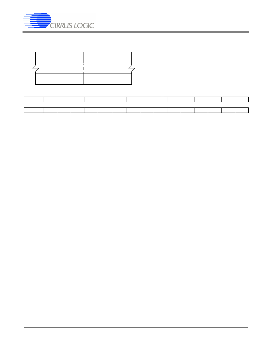
2.4.1. Channel-Setup Register Descriptions
CS1-CS0 (Channel Select Bits) [31:30] [15:14]
00
Select physical channel 1
01
Select physical channel 2
10
Select physical channel 3 (CS5534 only)
11
Select physical channel 4 (CS5534 only)
G2-G0 (Gain Bits) [29:27] [13:11]
For VRS = 0, A = 2; For VRS = 1, A = 1; Bipolar input span is twice the unipolar input span.
000
Gain = 1, (Input Span = [(VREF+)-(VREF-)]/1*A for unipolar).
001
Gain = 2, (Input Span = [(VREF+)-(VREF-)]/2*A for unipolar).
010
Gain = 4, (Input Span = [(VREF+)-(VREF-)]/4*A for unipolar).
011
Gain = 8, (Input Span = [(VREF+)-(VREF-)]/8*A for unipolar).
100
Gain = 16, (Input Span = [(VREF+)-(VREF-)]/16*A for unipolar).
101
Gain = 32, (Input Span = [(VREF+)-(VREF-)]/32*A for unipolar).
110
Gain = 64, (Input Span = [(VREF+)-(VREF-)]/64*A for unipolar).
WR3-WR0 (Word Rate) [26:23] [10:7]
The listed Word Rates are for continuous conversion mode using a 4.9152 MHz clock. All word rates will
scale linearly with the clock frequency used. The very first conversion using continuous conversion mode
will last longer, as will conversions done with the single conversion mode. See the section on Performing
Conversions and Tables 1 and 2 for more details.
Bit
WR (FRS = 0)
WR (FRS = 1)
0000
120 Sps
100 Sps
0001
60 Sps
50 Sps
0010
30 Sps
25 Sps
0011
15 Sps
12.5 Sps
0100
7.5 Sps
6.25 Sps
1000
3840 Sps
3200 Sps
1001
1920 Sps
1600 Sps
1010
960 Sps
800 Sps
1011
480 Sps
400 Sps
1100
240 Sps
200 Sps
All other combinations are not used.
D31(MSB) D30
D29
D28
D27
D26
D25
D24
D23
D22
D21
D20
D19
D18
D17
D16
CS1
CS0
G2
G1
G0
WR3
WR2
WR1
WR0
U/B
OL1
OL0
DT
OCD
OG1
OG0
D15
D14
D13
D12
D11
D10
D9
D8
D7
D6
D5
D4
D3
D2
D1
D0
CS1
CS0
G2
G1
G0
WR3
WR2
WR1
WR0
U/B
OL1
OL0
DT
OCD
OG1
OG0
CSR
#1
Setup 1
Bits <127:112>
Setup 2
Bits <111:96>
#4
Setup 7
Bits <31:16>
Setup 8
Bits <15:0>