System calibration, Calibration tips, System calibration 2.5.5. calibration tips – Cirrus Logic CS5534-BS User Manual
Page 32: Shown in figure 11. for accu, Vref- as shown in figure 12. self calibration of
CS5532/34-BS
32
DS755F3
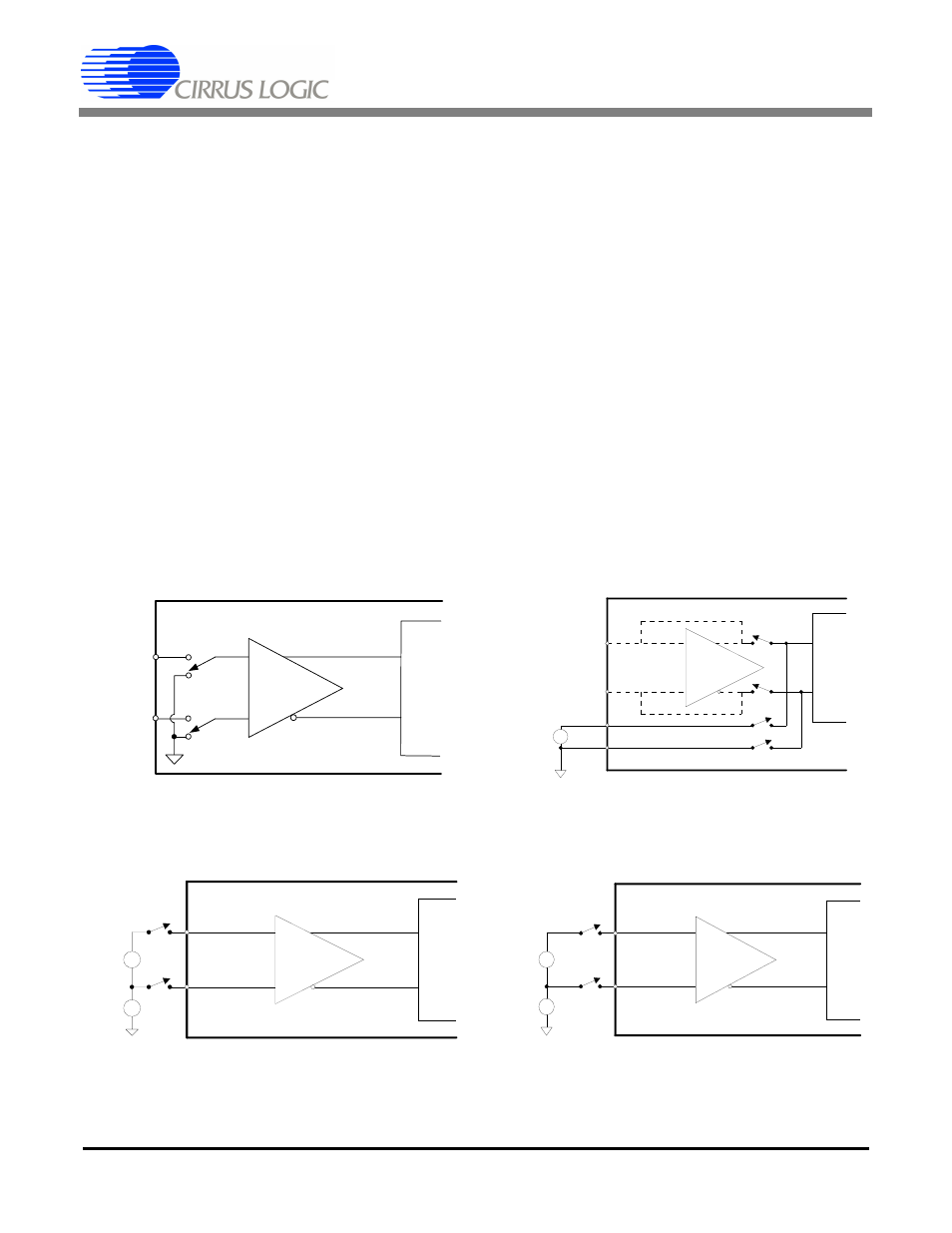
2.5.6. System Calibration
For the system calibration functions, the user must
supply the converter’s calibration signals which rep-
resent ground and full scale. When a system offset
calibration is performed, a ground-referenced signal
must be applied to the converters. Figure 13 illus-
trates system offset calibration.
As shown in Figure 14, the user must input a signal
representing the positive full-scale point to perform
a system gain calibration. In either case, the cali-
bration signals must be within the specified calibra-
tion limits for each specific calibration step (refer
to the System Calibration Specifications).
2.5.7. Calibration Tips
Calibration steps are performed at the output word
rate selected by the WR2-WR0 bits of the channel
setup registers. Due to limited register lengths in
the faster word-rate filters (240 Sps and higher),
channels that are used at these rates should also be
calibrated in one of these word rates, and channels
used in the lower word rates (120 Sps and lower)
should be calibrated at one of these lower rates.
Since higher word rates result in conversion words
with more peak-to-peak noise, calibration should
be performed at the lowest possible output word
rate for maximum accuracy. For the 7.5 Sps to
120 Sps word rate settings, calibrations can be per-
formed at 7.5 Sps, and for 240 Sps and higher, cal-
ibration can be performed at 240 Sps. To minimize
digital noise near the device, the user should wait
for each calibration step to be completed before
reading or writing to the serial port. Reading the
calibration registers and averaging multiple cali-
brations together can produce a more accurate cal-
ibration result. Note that accessing the ADC’s
serial port before a calibration has finished may re-
sult in the loss of synchronization between the mi-
+
+
_
_
AIN+
AIN-
1X GAIN
Figure 11. Self Calibration of Offset
AIN+
AIN-
OPEN
+
-
XGAIN
+
-
OPEN
CLOSED
VREF+
CLOSED
VREF-
+
-
Reference
Figure 12. Self Calibration of Gain
+
-
XGAIN
+
-
External
Connections
0V
+
-
AIN+
AIN-
CM +
-
Figure 13. System Calibration of Offset
+
-
XGAIN
+
-
External
Connections
Full Scale +
-
AIN+
AIN-
CM
+
-
Figure 14. System Calibration of Gain