Cirrus Logic CS5534-BS User Manual
Page 35
CS5532/34-BS
DS755F3
35
2.6.3. Examples of Using CSRs to Perform
Conversions and Calibrations
Any time a calibration or conversion command is
issued (C, MC, and CC2-CC0 bits must be properly
set), the CSRP2-CSRP0 bits in the command byte
are used as pointers to address one of the Setups in
the channel-setup registers (CSRs). Table 3 details
the address decoding of the pointer the bits.
The examples that follow detail situations that a
user might encounter when acquiring a conversion
or calibrating the converter. These examples as-
sume that the CSRs are programmed with the fol-
lowing physical channel order: 4, 1, 1, 2, 4, 3, 4, 4.
A physical channel is defined as the actual input
channel (AIN1 to AIN4) to which an external sig-
nal is connected.
Example 1: Single conversion using Setup 1. The
command issued is ‘10000000’. This instructs the
converter to perform a single conversion referenc-
ing Setup 1 (CSRP2 - CSRP0 = ‘000’) In this ex-
ample, Setup 1 points to physical channel 4. After
the command is received and decoded, the ADC
performs a conversion on physical channel 4 and
SDO falls to indicate that the conversion is com-
plete. To read the conversion, 40 SCLKs are then
required. Once the conversion data has been read,
the serial port returns to the command mode.
Example 2: Continuous conversions using Setup 3.
The command issued is ‘11010000’. This instructs
the converter to perform continuous conversions
referencing Setup 3 (CSRP2 - CSRP0 = ‘010’). In
this example, Setup 3 points to physical channel 1.
After the command is received and decoded, the
ADC performs a conversion on physical channel 1
and SDO falls to indicate that the conversion is
complete. The user now has three options. The user
can acquire the conversion and remain in this
mode, acquire the conversion and exit this mode, or
ignore the conversion and wait for a new conver-
sion at the next update interval, as detailed in the
continuous conversion section.
Example 3: Calibration using Setup 4. This exam-
ple assumes that the OGS bit in the Configuration
Register is set to ‘0’. The command issued is
‘10011001’. This instructs the converter to perform
a self offset calibration referencing Setup 4
(CSRP2 - CSRP0 = ‘011’). In this example, Setup
4 points to physical channel 2. After the command
is received and decoded, the ADC performs a self
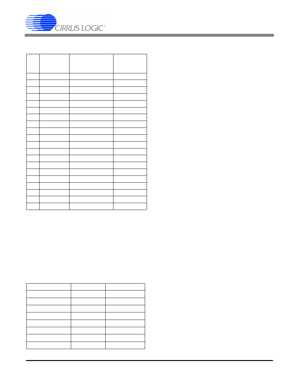
Table 2. Conversion Timing – Continuous Mode
FRS (WR3-WR0)
Clock Cycles
(First Conversion)
Clock Cycles
(All Other
Conversions)
0
0000
89528 ± 8
40960
0
0001
171448 ± 8
81920
0
0010
335288 ± 8
163840
0
0011
662968 ± 8
327680
0
0100
1318328 ± 8
655360
0
1000
2472 ± 8
1280
0
1001
12728 ± 8
2560
0
1010
17848 ± 8
5120
0
1011
28088 ± 8
10240
0
1100
48568 ± 8
20480
1
0000
107434 ± 10
49152
1
0001
205738 ± 10
98304
1
0010
402346 ± 10
196608
1
0011
795562 ± 10
393216
1
0100
1581994 ± 10
786432
1
1000
2966 ± 10
1536
1
1001
15274 ± 10
3072
1
1010
21418 ± 10
6144
1
1011
33706 ± 10
12288
1
1100
58282 ± 10
24576
Table 3. Command Byte Pointer
(CSRP2-CSRP0)
CSR Location
Setup
000
CSR #1
1
001
CSR #1
2
010
CSR #2
3
011
CSR #2
4
100
CSR #3
5
101
CSR #3
6
110
CSR#4
7
111
CSR #4
8