Cs5484, 52 peak current 1 (i1, Page 0, address 37 – Cirrus Logic CS5484 User Manual
Page 56: 53 peak voltage 1 (v1, Page 0, address 36
CS5484
56
DS981F3
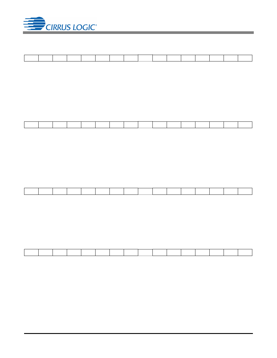
6.6.52 Peak Current 1 (I1
PEAK
) – Page 0, Address 37
Default = 0x00 0000
Peak current1 (I1
PEAK
) contains the value of the instantaneous current 1 sample with the greatest magnitude
detected during the last low-rate interval.
This is a two's complement value in the range of -1.0
value1.0, with the binary point to the right of the MSB.
6.6.53 Peak Voltage 1 (V1
PEAK
) – Page 0, Address 36
Default = 0x00 0000
Peak voltage 1 (V1
PEAK
) contains the value of the instantaneous voltage 1 sample with the greatest magni-
tude detected during the last low-rate interval.
This is a two's complement value in the range of -1.0
value 1.0, with the binary point to the right of the MSB.
6.6.54 Apparent Power 1 (S1) – Page 16, Address 20
Default = 0x00 0000
Apparent power 1 (S1) is the product of V1
RMS
and I1
RMS
or SQRT(P1
AVG
2
+ Q1
AVG
2
).
This is an unsigned value in the range of 0
value 1.0, with the binary point to the right of the MSB.
6.6.55 Power Factor 1 (PF1) – Page 16, Address 21
Default = 0x00 0000
Power factor 1 (PF1) is calculated by dividing active power 1 (P1
AVG
) by apparent power 1 (S1).
The sign is determined by the active power (P1
AVG
) sign.
This is a two's complement value in the range of -1.0
value 1.0, with the binary point to the right of the MSB.
MSB
LSB
-(2
0
)
2
-1
2
-2
2
-3
2
-4
2
-5
2
-6
2
-7
.....
2
-17
2
-18
2
-19
2
-20
2
-21
2
-22
2
-23
MSB
LSB
-(2
0
)
2
-1
2
-2
2
-3
2
-4
2
-5
2
-6
2
-7
.....
2
-17
2
-18
2
-19
2
-20
2
-21
2
-22
2
-23
MSB
LSB
0
2
-1
2
-2
2
-3
2
-4
2
-5
2
-6
2
-7
.....
2
-17
2
-18
2
-19
2
-20
2
-21
2
-22
2
-23
MSB
LSB
-(2
0
)
2
-1
2
-2
2
-3
2
-4
2
-5
2
-6
2
-7
.....
2
-17
2
-18
2
-19
2
-20
2
-21
2
-22
2
-23