4 line frequency measurement, 5 energy pulse generation, Cs5484 – Cirrus Logic CS5484 User Manual
Page 22
CS5484
22
DS981F3
5.4 Line Frequency Measurement
If the Automatic Frequency Calculation (AFC) bit in the
Config2 register is set, the line frequency measurement
on the voltage channel will be enabled. The line
frequency measurement is based on a number of
voltage channel zero crossings. This number is 100 by
default and configurable through the ZX
NUM
register
(see section
on page 61). The Epsilon register
will be updated automatically with the line frequency
information. The Frequency Update (FUP) bit in the
Status0 interrupt status register is set when the
frequency calculation is completed. When the line
frequency is 50Hz and the ZX
NUM
register is 100, the
Epsilon register is updated every one second with a
resolution of less than 0.1%. A larger zero-crossing
number in the ZX
NUM
register will increase line
frequency measurement resolution and the period. Note
that the CS5484 line frequency measurement function
does not support the line frequency out of the range of
40Hz to 75Hz.
The Epsilon register is also used to set the gain of the
90° phase shift filter used in the quadrature power
calculation. The value in the Epsilon register is the ratio
of the line frequency to the output word rate (OWR). For
50Hz line frequency and 4000Hz OWR, Epsilon is
50/4000 (0.0125) (the default). For 60Hz line
frequency, it is 60/4000 (0.015).
5.5 Energy Pulse Generation
The CS5484 provides four independent energy pulse
generation blocks (EPG1, EPG2, EPG3, and EPG4) in
order to simultaneously output active, reactive, and
apparent energy pulses on any of the four digital output
pins (DO1, DO2, DO3, and DO4). The energy pulse
frequency is proportional to the magnitude of the power.
The energy pulse output is commonly used as the test
output of a power meter. The host microcontroller can
also use the energy pulses to easily accumulate the
energy. Refer to
.
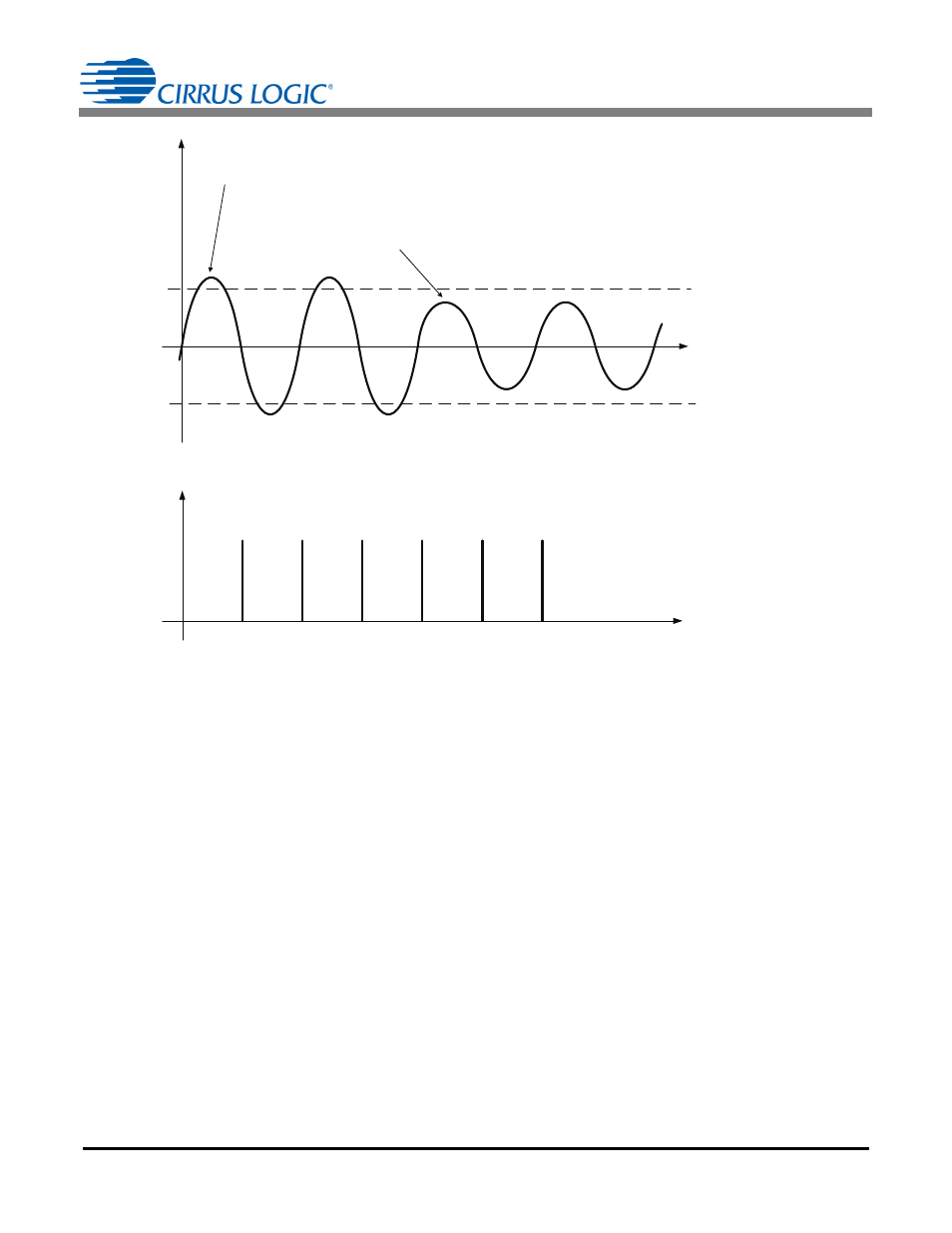
VZX
LEVEL
IZX
LEVEL
If |V
PEAK
|
> VZX
LEVEL
, then voltage zero-crossing detection is enabled.
If |I
PEAK
|
> IZX
LEVEL
, then current zero-crossing detection is enabled.
Zero-crossing output on DOx pin
Pulse width = 250μs
V(
t), I(t)
DOx
t
t
If |V
PEAK
|
VZX
LEVEL
, then voltage zero-crossing detection is disabled.
If |I
PEAK
|
IZX
LEVEL
, then current zero-crossing detection is disabled.
Figure 13. Zero-crossing Level and Zero-crossing Output on DOx