Vt100 rs-232 interface, Figure 1-5, Bbp block diagram – ADTRAN Tracer 2 x E1 User Manual
Page 14
TRACER 2 x E1 User’s Manual
61280004L2-1C
Section 1 TRACER Description
4
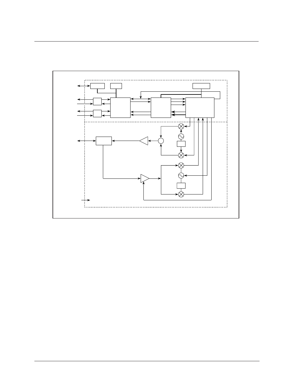
A block diagram of the BBP is shown in Figure 1-5.
VT100 RS-232 Interface
An RS-232 interface is provided via a 25-pin D connector for attaching a VT100 compatible terminal.
The active signals used on this interface are listed below
Signal Name
Pin Number
Source
Transmit Data .......... 2 ............. Terminal/Modem
Receive Data ............ 3 ............. TRACER
Request to Send ....... 4 ............. Terminal/Modem
Clear to Send ............ 5 ............. TRACER
Data Set Ready ........ 6 ............. TRACER
Signal Ground .......... 7
The management system allows the E1 interfaces to be provisioned. The line code can be selected as
AMI or HDB3. The signaling can be selected as channel associated signaling (CAS) or common channel
signaling (CCS). Alarm conditions can also be monitored. The management system will report the
following alarms on the E1 interfaces:
Figure 1-5. BBP Block Diagram
Σ
E1
Data
Multiplexer
Viterbi
Encoder/
Decoder
Spread
Spectrum
Data
Pump
90
90
Baseband Processor Board
IF Interface Board
Fc = 70 MHz
Fc = 140 MHz
Filter
µC
UART
DSP
21-56
VDC
RS-232
E1 A
IF
E1
E1 B