E1 interfaces, Tracer system configuration, Baseband processor or bbp – ADTRAN Tracer 2 x E1 User Manual
Page 13: Figure 1-3, Figure 1-4, Bbp rear panel, Figure 1-4. bbp rear panel (75, Option) figure 1-3. bbp, Tracer 2 x e1 user’s manual
TRACER 2 X E1 User’s Manual
61280004L2-1C
Section 1 TRACER Description
3
E1 Interfaces
The E1 interfaces conform to the ITU G.703 and G.704 electrical and signaling interface
recommendations. Two interfacing configurations are allowed - two pair of BNC coaxial connectors or
two 15-pin sub-D connectors and RJ48 connectors.
The coaxial connection provides a 75
Ω unbalanced connection. The shield of the TX coaxial connection
is attached to earth ground. A strap is provided to optionally connect the shield of the RX coaxial
connection to ground as described in G.703. The 15 pin sub-D and RJ48 connection provides a 120
Ω
balanced connection.
TRACER System Configuration
A TRACER system is composed of three major subsystems -- a baseband processor, a radio frequency
converter, and an antenna. The following section describes the system components.
Baseband Processor or BBP
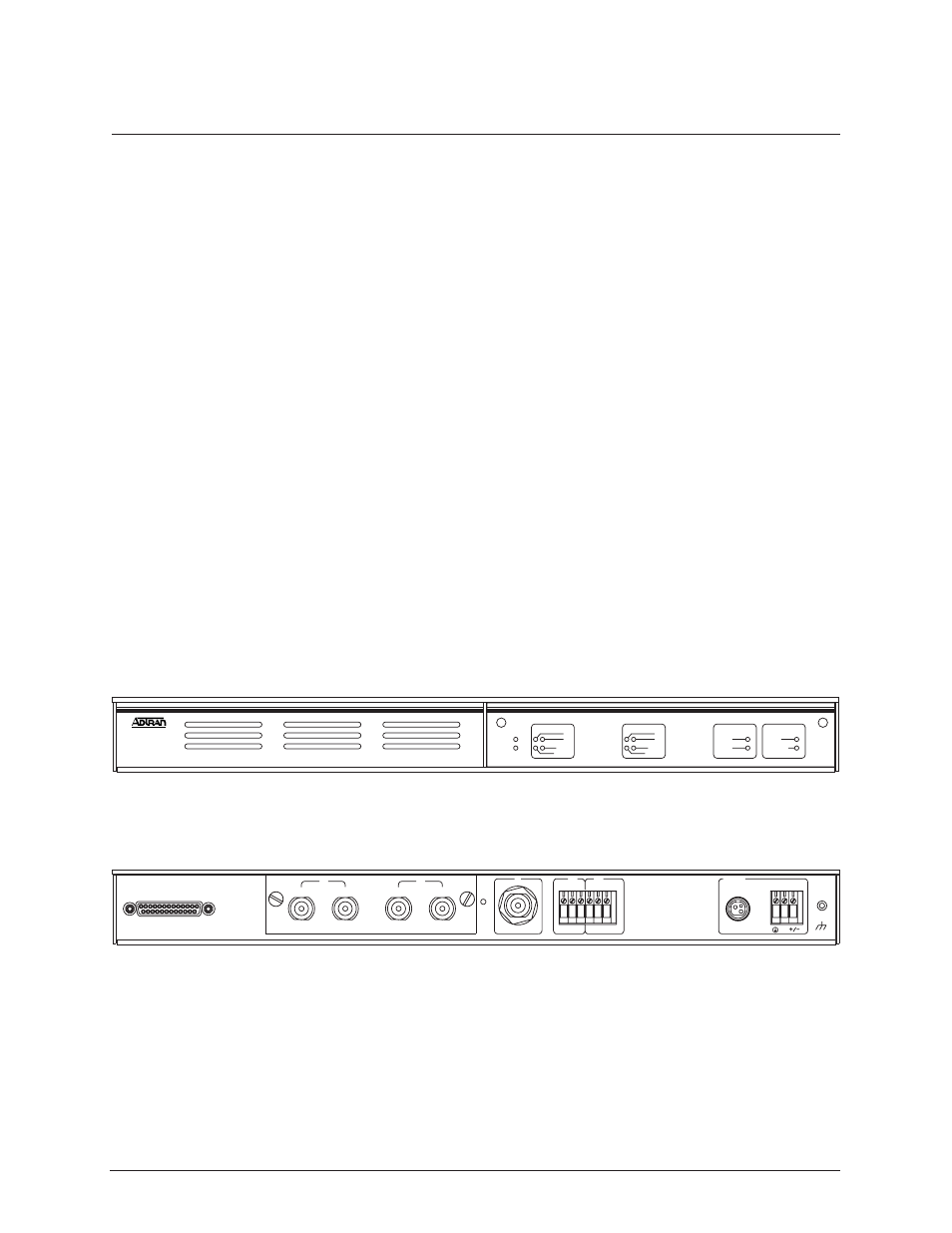
The baseband processor or BBP is a 1-U, 515 mm (19-inch) rackmountable unit. This unit provides the
system electrical interfaces, user controls and indicators, and performs the spread spectrum processing
for the system. The rear panel provides all of the electrical interface points -- E1 interfaces, VT100
compatible terminal, alarm contacts, IF signal, and DC power (from facility or optional AC adapter).
The BBP front and rear panels are illustrated in Figures 1-3 and 1-4.
Figure 1-4. BBP Rear Panel (75
Ω
Option)
Figure 1-3. BBP
ALM
E1A
LBK
LOS/OOF
CV/CRC
LOS/OOF
CV/CRC
ALM
E1B
LBK
FREQ
PLAN A
PLAN B
TEST
POWER
RF LOW
LINK DOWN
SYSTEM
TRACER
RS232
G.703
IF
MAJ
NO COM
NC
NO COM NC
MIN
DC POWER
E1A
75 OHM
RX
TX
E1B
75 OHM
RX
TX