8 register description, 1 device and revision id - register 01h, 2 mode control - register 02h – Cirrus Logic CS4349 User Manual
Page 29: 1 digital interface format (dif[2:0]) bits 6-4, Table 14. digital interface formats, Section 8.2.1
DS782F2
29
CS4349
8 REGISTER DESCRIPTION
Note: All register access is R/W unless specified otherwise.
8.1
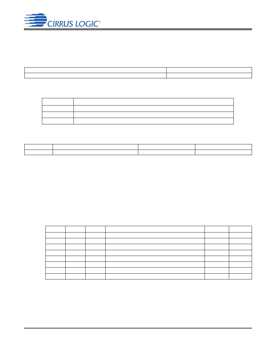
Device and Revision ID - Register 01h
Function:
This register is Read-Only. It is decoded as follows:
8.2
Mode Control - Register 02h
8.2.1
Digital Interface Format (DIF[2:0]) Bits 6-4
Function:
These bits select the interface format for the serial audio input.
The required relationship between the Left/Right clock, serial clock and serial data is defined by the Digital
Interface Format and the options are detailed in
Note:
The group delay for TDM slot 0 channel B differs from the group delay of all other interface for-
mats and TDM slots/channels by one sample. Refer to the group delay specification in the combined in-
terpolation and on-chip analog filter response specifications table.
7
6
5
4
3
2
1
0
Device4
Device3
Device2
Device1
Device0
Rev2
Rev1
Rev0
1
1
1
1
-
-
-
-
Rev
Register 01h contents
A
1111,0000
B
1111,0001
C2
1111,1111
7
6
5
4
3
2
1
0
Reserved
DIF2
DIF1
DIF0
DEM1
DEM0
FM1
FM0
0
0
0
0
0
0
0
0
DIF2
DIF1
DIF0
Description
Format
Figure
0
0
0
Left-Justified, up to 24-bit data
0
(Default)
0
0
1
I²S, up to 24-bit data
1
0
1
0
Right-Justified, 16-bit data
2
0
1
1
Right-Justified, 24-bit data
3
1
0
0
TDM slot 0
4
1
0
1
TDM slot 1
5
1
1
0
TDM slot 2
6
1
1
1
TDM slot 3
7
Table 14. Digital Interface Formats