3 digital interface format, Figure 11. left-justified up to 24-bit data, Figure 12. i²s, up to 24-bit data – Cirrus Logic CS4349 User Manual
Page 19: Figure 13. right-justified data, Refer to, Section 4.3, Cs4349
DS782F2
19
CS4349
4.3
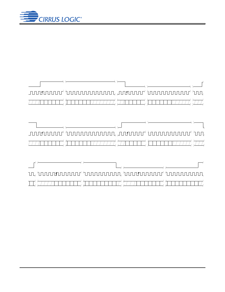
Digital Interface Format
The device will accept audio samples in 1 of 8 digital interface formats, as shown in
for Stand-Alone Mode and
The desired serial audio interface format is selected via the DIF[2:0] bits in Control Port Mode (see
), or the DIF[2:0] pins in Stand-Alone Mode (see
). For illustrations of the required
relationship between LRCK, SCLK and SDIN, see
. For all formats, SDIN is valid on the rising
edge of SCLK.
For more information about serial audio formats, refer to the Cirrus Logic Application Note AN282,
The 2-Channel Serial Audio Interface: A Tutorial, available at
.cirrus.com
.
+3
+2
+1
+5
+4
MSB
-1
-2
-3
-4
-5
+3
+2
+1
+5
+4
-1
-2
-3
-4
LSB
MSB
LSB
Left Channel
Right Channel
LRCK
SCLK
SDIN
Figure 11. Left-Justified up to 24-Bit Data
+3
+2
+1
+5
+4
MSB
-1
-2
-3
-4
-5
+3
+2
+1
+5
+4
-1
-2
-3
-4
MSB
LSB
LSB
Left Channel
Right Channel
LRCK
SCLK
SDIN
Figure 12. I²S, up to 24-Bit Data
SDIN
+6
+5
+4
+3
+2
+1
+7
-1
-2
-3
-4
-5
LSB
LSB
MSB
-1
-2
-3
-4
-5
LSB
+6
+5
+4
+3
+2
+1
+7
MSB
Left Channel
Right Channel
LRCK
SCLK
Figure 13. Right-Justified Data