1 time-division multiplex (tdm) mode, Figure 14. tdm mode connection diagram, Figure 15. tdm mode timing – Cirrus Logic CS4349 User Manual
Page 20: Cs4349
20
DS782F2
CS4349
4.3.1
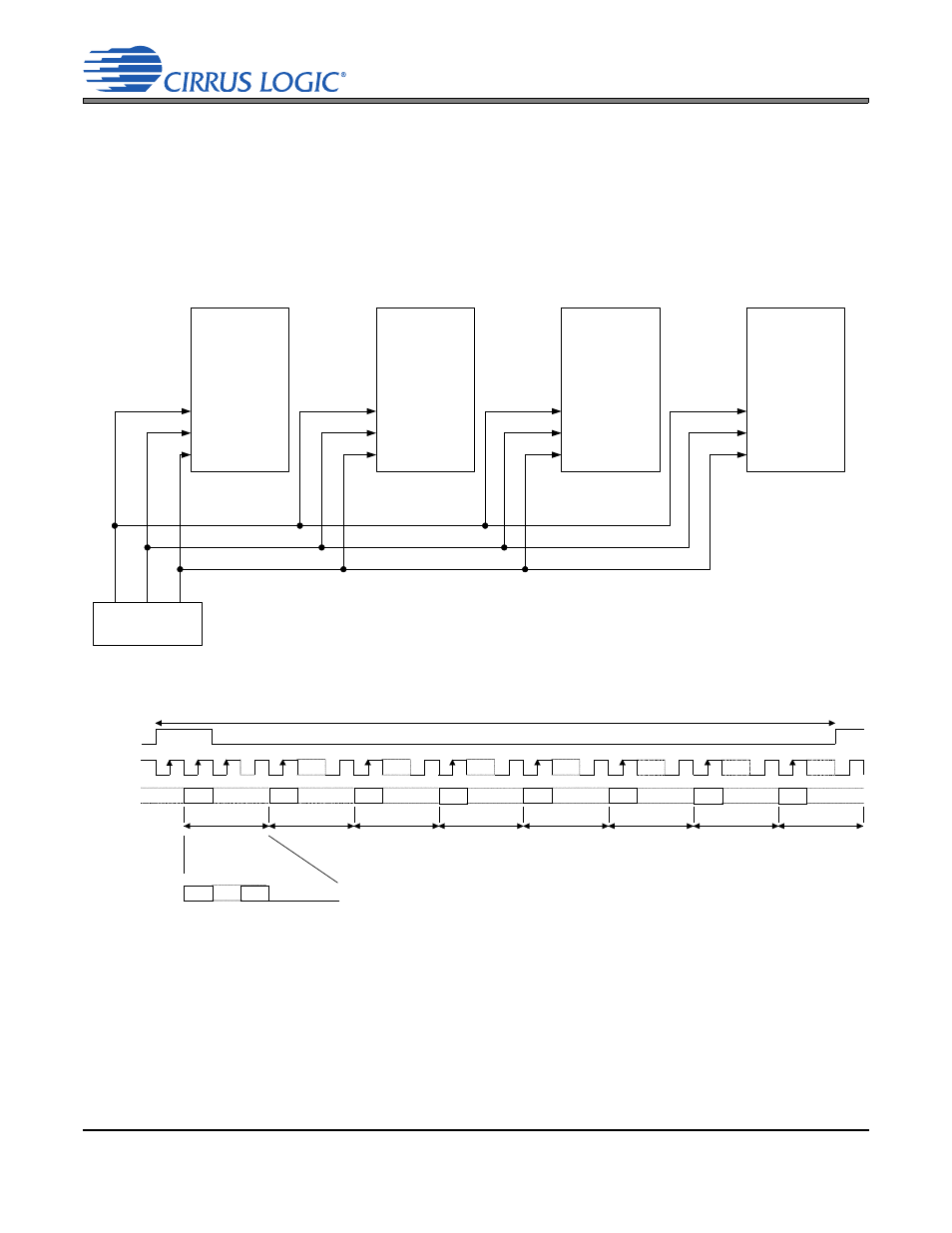
Time-Division Multiplex (TDM) Mode
Four TDM interface modes are available that allow the CS4349 to input stereo PCM data in one of four
time “slots”.
shows the serial port connections necessary to input eight-channel TDM data into
four CS4349 devices and the corresponding DIF[2:0] pin or register-bit settings required for each CS4349.
shows the TDM data format for each of the four CS4349 devices shown in
.
Note:
The group delay for TDM slot 0 channel B differs from the group delay of all other interface for-
mats and TDM slots/channels by one sample. Refer to the group delay specification in the combined in-
terpolation and on-chip analog filter response specifications table.
.
Figure 14. TDM Mode Connection Diagram
LRCK
SCLK
SDIN
ILRCK
ISCLK
SDIN
LRCK
SCLK
SDIN
LRCK
SCLK TDM_OUT
TDM Source
LRCK
SCLK
SDIN
DIF[2:0] = 100
DIF[2:0] = 101
DIF[2:0] = 110
DIF[2:0] = 111
CS4349
4
CS4349
1
CS4349
3
CS4349
2
Slot 1, ch B
LRCK
SCLK
MSB
MSB
MSB
MSB
MSB
SDIN1
Slot 3, ch A
Slot 3, ch B
Slot 1, ch A
Slot 0, ch A
256 clks
32 clks
32 clks
32 clks
32 clks
32 clks
MSB
Slot 2, ch A
32 clks
MSB
Slot 0, ch B
32 clks
MSB
Slot 2, ch B
32 clks
LSB
MSB
zero
Data
Figure 15. TDM Mode Timing