Figure 6. serial port timing, non-tdm mode, Figure 7. serial port timing, tdm mode, Figure 8. control port timing - i²c format – Cirrus Logic CS4349 User Manual
Page 14: Figure 6, Figure 7, Cs4349
14
DS782F2
CS4349
.
2.7
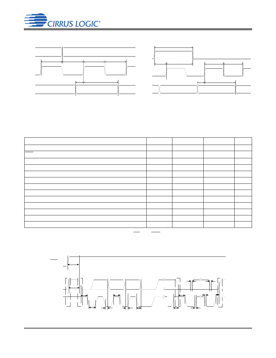
Switching Characteristics - Control Port - I²C Format
Inputs: Logic 0 = GND; Logic 1 = VLC; C
L
= 20 pF.
Notes: 9. t
spi
only needed before first falling edge of CS after RST rising edge. t
spi
= 0 at all other times.
Data must be held for sufficient time to bridge the transition time, t
fc
, of SCL.
Table 8. Switching Characteristics - Control Port - I²C Format
Parameter
Symbol
Min
Max
Unit
SCL Clock Frequency
f
scl
-
100
kHz
RST Rising Edge to Start
t
irs
500
-
ns
Bus Free Time Between Transmissions
t
buf
4.7
-
µs
Start Condition Hold Time (prior to first clock pulse)
t
hdst
4.0
-
µs
Clock Low time
t
low
4.7
-
µs
Clock High Time
t
high
4.0
-
µs
Setup Time for Repeated Start Condition
t
sust
4.7
-
µs
SDA Hold Time from SCL Falling
t
hdd
0
-
µs
SDA Setup time to SCL Rising
t
sud
250
-
ns
Rise Time of SCL and SDA
t
rc
, t
rc
-
1
µs
Fall Time SCL and SDA
t
fc
, t
fc
-
300
ns
Setup Time for Stop Condition
t
susp
4.7
-
µs
Acknowledge Delay from SCL Falling
t
ack
300
1000
ns
t
ds
LRCK
(Input)
t
dh
t
sckh
t
sckl
t
fsh
t
fss
SCLK
(Input)
SDIN
(Input)
MSB
MSB-1
t
lrckh
t
ds
MSB
t
dh
MSB-1
LRCK
(input)
SCLK
(input)
SDIN
(input)
t
sckh
t
sckl
t
lcks
t
lckd
Figure 6. Serial Port Timing, Non-TDM Mode
Figure 7. Serial Port Timing, TDM Mode
t buf
t hdst
t
lo w
t
hdd
t high
t sud
Stop
Start
S D A
S C L
t irs
R S T
t
hdst
t rc
t fc
t sust
t susp
Start
Stop
R epe ate d
t rd
t fd
t ack
Figure 8. Control Port Timing - I²C Format