Specifications / 4. design and function, Design and function – WIKA Hydra-Gauge User Manual
Page 7
WIKA operating instructions HYDRA-Gauge
7
9015329.01 08/2013 GB/D/F/E
GB
3. Specifications / 4. Design and function
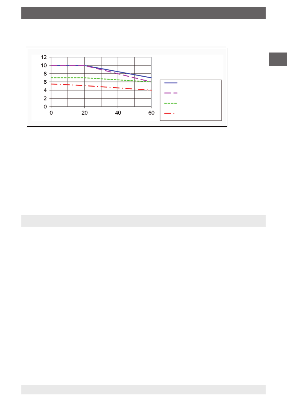
Permissible process pressure
■
The HYDRA-Gauge is not appropriate for strong vibrations, pulsations and pressure
surges, e.g. at measuring points directly behind a pump. Appropriate pulsation dampers
and restrictor segments may be necessary.
■
The HYDRA-Gauge must not be used with aggressive ambient conditions (e.g. HCl
vapours). This may result in corrosion of the metallic parts of the HYDRA-Gauge.
For further specifications see WIKA data sheet SP 99.20 and the order documentation.
Temperature in °C
Pr
essur
e in bar
1/4" and 3/8"
1/2"
3/4"
1"
1 1/4"
only up to
25 °C
4. Design and function
4.1 Description
HYDRA-Gauge is a mechanical pressure gauge of nominal size 63 in accordance with
EN 837-1. With a special diaphragm seal system it has been adapted to the special
requirements of ultrapure media distribution systems. All wetted parts are made of PFA
or TFM (modified PTFE). Final assembly, adjustment and packaging is effected under
Laminar-Flow Class 100. Standard system fill fluid is KN 75, a 50/50 mixture of DI water and
isopropyl alcohol (IPA). Optionally DI water (KN 64) is used. Pressure gauge and diaphragm
seal are one unit and may never ever be separated as this may cause the system fill fluid to
leak, thus destroying the measuring assembly.
4.2 Scope of delivery
Cross-check scope of delivery with the delivery note.