Hydra-gauge with switch contacts – WIKA Hydra-Gauge User Manual
Page 10
10
WIKA operating instructions HYDRA-Gauge
9015329.01 08/2013 GB/D/F/E
GB
7. HYDRA-Gauge with switch contacts
7.2 Special requirements for the installation point
To avoid, amongst other things, switch signal "chatter", it must be ensured that the instru-
ments are mounted free of vibration.
7.3 Electrical connection
The electrical connection must only be made by qualified skilled personnel. The permis-
sible electrical data, connection details and switching functions are given on the product
label affixed to the instrument.
The connection cables are appropriately marked.
■
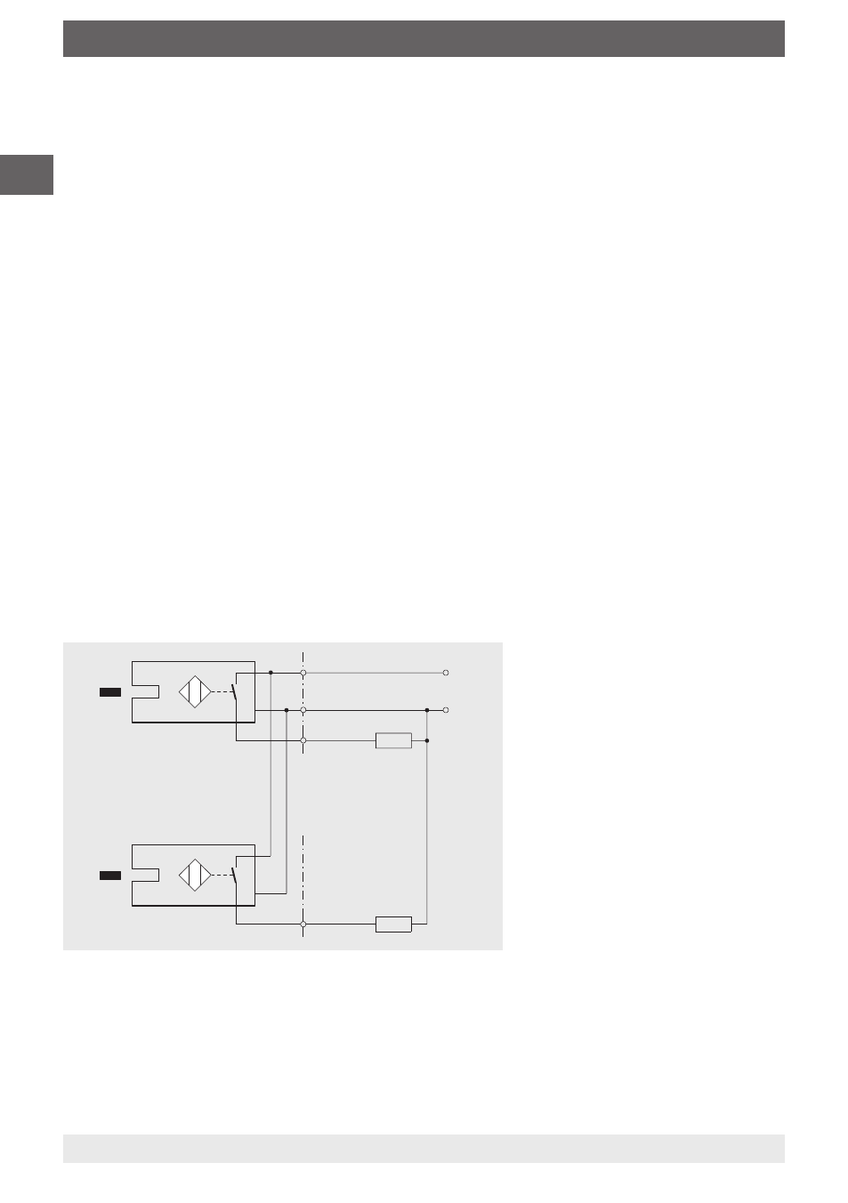
To connect a PLC control unit or for direct switching of small capacities
■
PNP transistor
With PNP switching apparatus, the switched output is a connection towards PLUS. The
load RL between the switched ouput and the MINUS should be selected in a way not to
exceed the maximum switching current of 100 mA.
RL (load)
RL (2nd load)
With double contact
PNP
PNP
2
1
3
4
+ U
B
_
2nd contact
■
Flag emerges from slot
sensor:
Contact open
(output not active)
■
Flag retreats into slot sensor:
Contact closed (output active)
Connection and function circuit diagrams for electronic contact model 830 E,
3-wire system,
control and switching electronics in the sensor,
electrical connection via flying leads