WIKA DPT-10 User Manual
Page 11
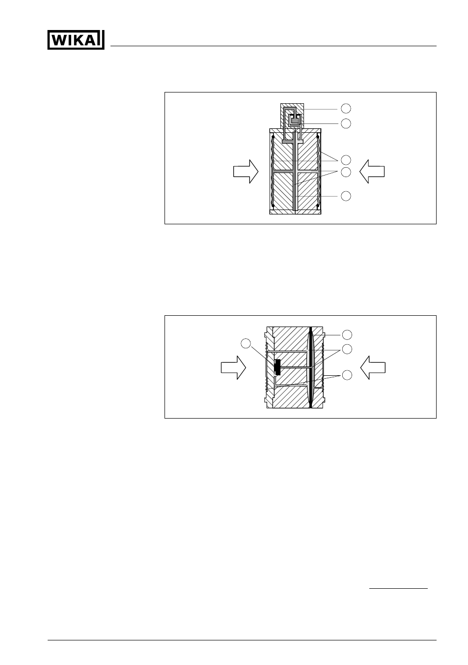
The configuration of the measuring cells differs depending on the
measuring range:
1
2
3
4
5
1
p
2
p
Fig. 7: Metallic measuring cell 10 mbar and 30 mbar - p
1
and p
2
process
pressures
1
Measuring element
2
Silicone diaphragm
3
Separating diaphragm
4
Filling oil
5
Integrated overvoltage arrester
1
p
2
p
1
2
3
4
Fig. 8: Metallic measuring cell from 100 mbar - p
1
and p
2
process pressures
1
Measuring element
2
Overload diaphragm/Middle diaphragm
3
Filling oil
4
Separating diaphragm
Power supply via the Profibus DP/PA segment coupler. A two-wire
cable according to Profibus specification serves as carrier of both
power and digital data transmission for multiple sensors. The
instrument profile of DPT10 corresponds to profile specification
version 3.0.
The GSD (instrument master files) and bitmap files necessary for
planning your Profibus DP (PA) communication network are available
from the download section on the WIKA homepage www.wika.com
under "Service". There you can also find the appropriate certificates. In
Power supply and bus
communication
GSD/EDD
Differential pressure transmitter DPT10 - metal measuring diaphragm • Profibus PA
11
3 Product description
37245
-
EN
-100120