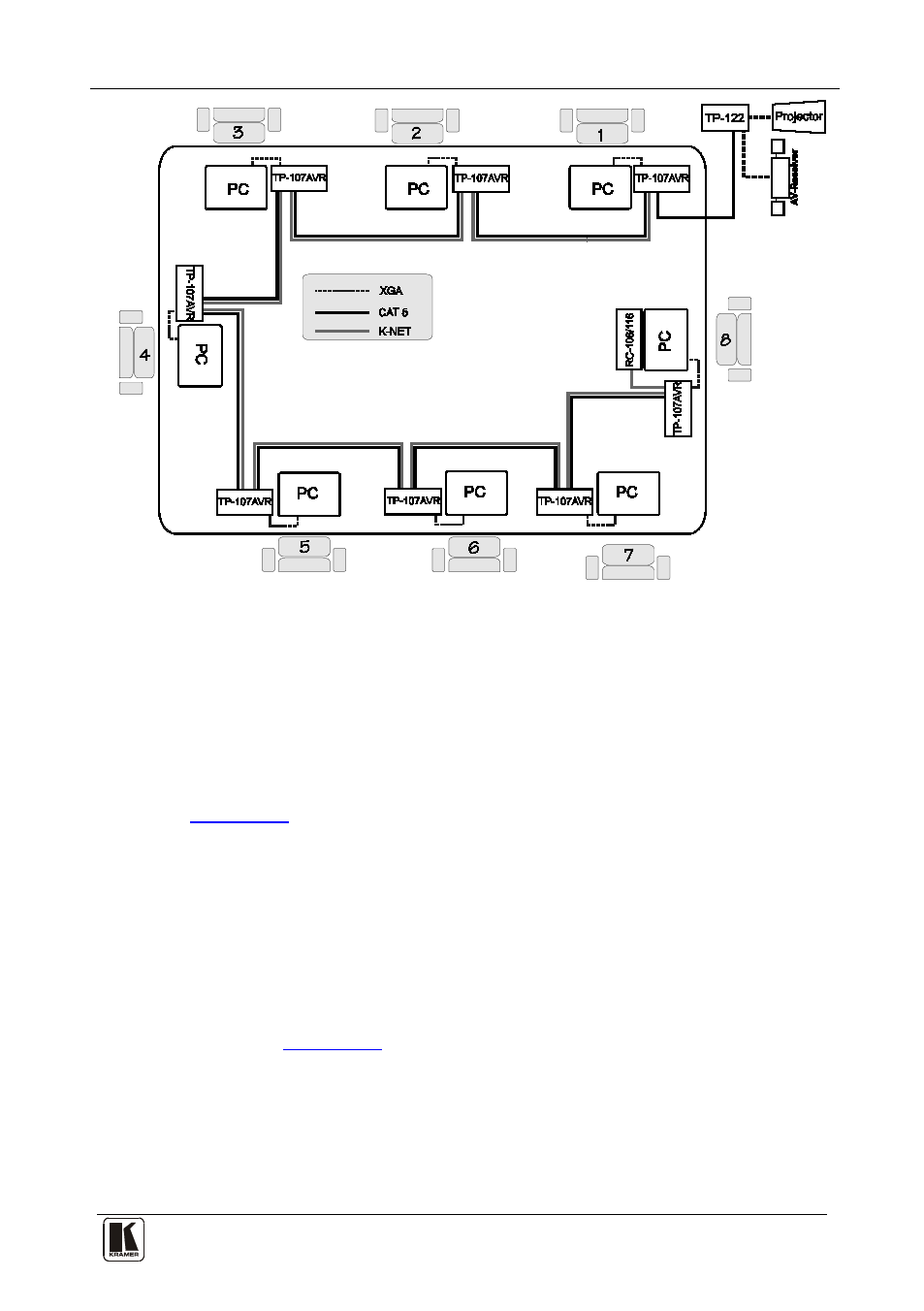
Figure 1: tp-107avr/tp-122 configuration, Figure 1 – Kramer Electronics TP-107AVR User Manual
Page 8
Overview
5
5
Figure 1: TP-107AVR/TP-122 Configuration
The TP-107AVR includes:
•
A LINE IN CAT 5 connector, that connects to the LINE OUT CAT 5
connector on the previous Line Transmitter
•
A LINE OUT CAT 5 connector, that connects to a receiver (for
example, the TP-122) or to the next Line Transmitter in the chain
•
A pair of rotary selector switches for setting the ADDRESS (see
Section 5.6
In addition, the TP-107AVR:
•
Must be controlled via KNET
•
Has a resolution of up to UXGA
•
Is 12V DC fed
The TP-122:
•
Can power—or be powered by—the transmitter over the same CAT 5
cable (see
Section 3.4
•
Can change the polarity of decoding H and V Sync for video
•
Includes EQ. and level controls
•
Allows an operation range of more than 300ft (more than 100m) over
standard CAT 5 cable
•
Is 12V DC fed