2 connecting the tp-107avr/tp-122 boardview™ kit, Connecting the tp-107avr/tp-122 boardview™ kit, Figure 10: connecting the tp-107avr – Kramer Electronics TP-107AVR User Manual
Page 18: N 5.2
Configuring a TP-107AVR System
15
15
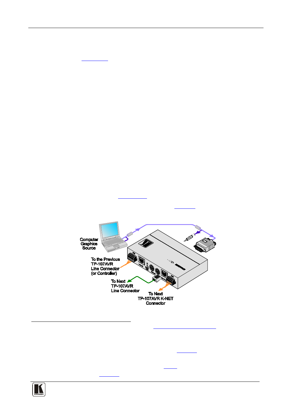
5.2 Connecting the TP-107AVR/TP-122 BoardView™ Kit
To connect the TP-107AVR/TP-122 BoardView™ kit as illustrated in the
example in
, do the following:
1. Connect an XGA source (for example, a computer graphics source) to
the XGA IN 15-pin HD computer graphics connector and an audio
source to the audio IN 3.5mm mini jack, for example, using a Kramer
C-GMA/GMA cable (VGA 15-pin HD (M) + audio jack to VGA
15-pin HD (M) + audio jack)
2. Connect the LINE OUT RJ-45
.
connector to the LINE IN RJ-45
connector on the next TP-107AVR in the chain or to the LINE IN
RJ-45 connector of a receiver (for example, the Kramer TP-122), via
STP cabling
3. Connect the LINE OUT RJ-45 connector of the previous TP-107AVR
unit to the LINE IN RJ-45 connector on the TP-107AVR.
. The total range of the connected units should be no
more than 300ft (100m).
4. Connect the K-NET
port to the previous and the next TP-107AVR
unit or to the RC-108 Presentation Controller
5. Set an address number for each TP-107AVR unit via the two
potentiometers (see
Section 5.6
6. Connect the 12V DC power supply (see
) to the power socket
and connect the power supply to the mains electricity.
Figure 10: Connecting the TP-107AVR
1 Not supplied. The full list of Kramer cables is on our Web
Alternatively, you can
connect an XGA source to the XGA IN 15-pin HD computer graphics connector, and a separate audio source to the AUDIO
IN 3.5mm mini jack
2 For details of how to wire a CAT 5 LINE IN/LINE OUT RJ-45 connector, see
Section 5.4
3 The Kramer BC-STP cable is recommended
4 The 12V DC power supply (provided) is used to power the system (see
5 Or alternatively to the RC-116 (see