1 rs-485 communication protocol, Rs-485 communication protocol – Kramer Electronics TP-107AVR User Manual
Page 24
Controlling the TP-107AVR
21
21
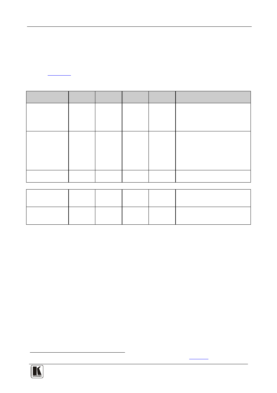
6.2.1 RS-485 Communication Protocol
Use the communication protocol to control the TP-107AVR units via an
RS-485 controller. The communication settings are: 9600 bps, 8 data bits,
no parity, 1 stop bit and no flow control.
defines the communication protocol for address numbers 0 to 127.
Table 11: RS-485 Communication Protocol (Address Number 0 – 127)
Command:
Command
1
Command
2
Command
3
Command
4
Description:
Select a
TP-107AVR
machine according
to its address
number
H02
H81
H80 +
Address1
H81
The VGA input of the selected
TP-107AVR device is activated.
VGA inputs of other
TP-107AVR
units in the chain are blocked
Free Speech
H02
H82
H80 +
Address1
H81
Following this command, any
TP-107AVR in the chain can be
activated by pressing the ONLINE
button. This state is cancelled after
the "Select
TP-107AVR Machine"
command is sent to any
TP-107AVR
in the chain
Turn OFF a
TP-107AVR
H02
H83
H80 +
Address1
H81
The VGA input of the selected
TP-107AVR device is blocked
The
TP-107AVR replies:
In Free Speech
mode the ONLINE
button is ON
H45
H81
H80 +Addr H81
Reply sent from the specific
TP-107AVR to the controller
In Free Speech
mode the ONLINE
button is OFF
H45
H80
H80 +Addr H81
Reply sent from the specific
TP-107AVR to the controller
1 The address number of the selected TP-107AVR as set by the rotary address switches (see