Figure 7: rc-108 underside panel, Figure 8: rc-116 underside panel, Table 8: rc-108/rc-116 (underside panel) features – Kramer Electronics TP-107AVR User Manual
Page 15
KRAMER: SIMPLE CREATIVE TECHNOLOGY
Your Line Transmitter, Receiver and Presentation Controllers
12
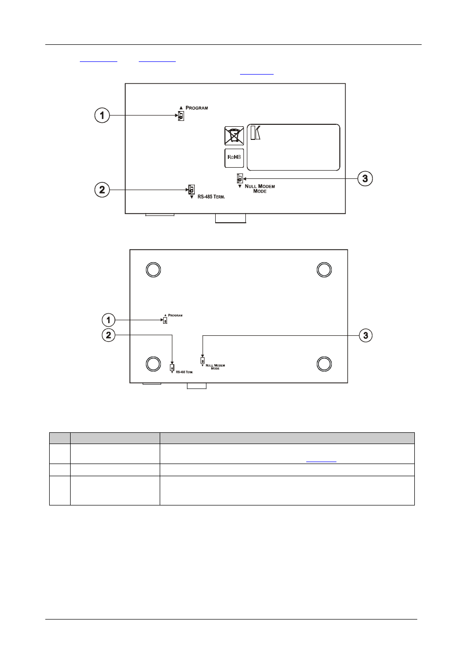
illustrate the underside of the RC-108 and the
RC-116, respectively, as defined in
Figure 7: RC-108 Underside Panel
Figure 8: RC-116 Underside Panel
Table 8: RC-108/RC-116 (Underside Panel) Features
#
Feature
Function
1
PROGRAM Switch
Slide downwards for normal operation, slide upwards to PROGRAM to
upgrade to the latest Kramer firmware (see
Section 8
2
),
RS-485 TERM. Switch Slide the switch downwards to terminate the RS-485 Line with 120Ω
3
NULL MODEM MODE
Switch
To connect a PC to the unit using a null-modem adapter, slide the NULL
MODEM MODE switch downwards, otherwise connect without a null-
modem adapter