7 installing a remote button, Installing a remote button, Table 13: remote pinout – Kramer Electronics TP-107AVR User Manual
Page 25: On 7, 7installing a remote button
KRAMER: SIMPLE CREATIVE TECHNOLOGY
Installing a Remote Button
22
defines the Communication protocol for address numbers 128 to
255
Table 12: RS-485 Communication Protocol (Address Number 128 – 255)
Command:
Command
1
Command
2
Command
3
Command
4
Description:
Select a
TP-107AVR
machine according
to its address
number
H02
H81
Address1
HC1
The VGA input of the selected
TP-107AVR device is activated.
VGA inputs of other
TP-107AVR
units in the chain are blocked
Free Speech
H02
H82
Address1
HC1
Following this command, any
TP-107AVR in the chain can be
activated by pressing the ONLINE
button. This state is cancelled after
the "Select
TP-107AVR Machine"
command is sent to any
TP-107AVR
in the chain
Turn OFF a
TP-107AVR
H02
H83
Address1
HC1
The VGA input of the selected
TP-107AVR device is blocked
The
TP-107AVR replies:
In Free Speech
mode the ONLINE
button is ON
H45
H81
Address1
HC1
Reply sent from the specific
TP-107AVR to the controller
In Free Speech
mode the ONLINE
button is OFF
H45
H80
Address1
HC1
Reply sent from the specific
TP-107AVR to the controller
For example:
•
Select TP-107AVR machine 5:
Hx02,Hx81,Hx85,Hx81
•
Select TP-107AVR machine 200 (HxC8):
Hx02,Hx81,HxC8,HxC1
•
Select TP-107AVR machine 100 (Hx64):
Hx02,Hx81,HxE4,Hx81
Calculation – Hx80+Hx64 = HxE4
7
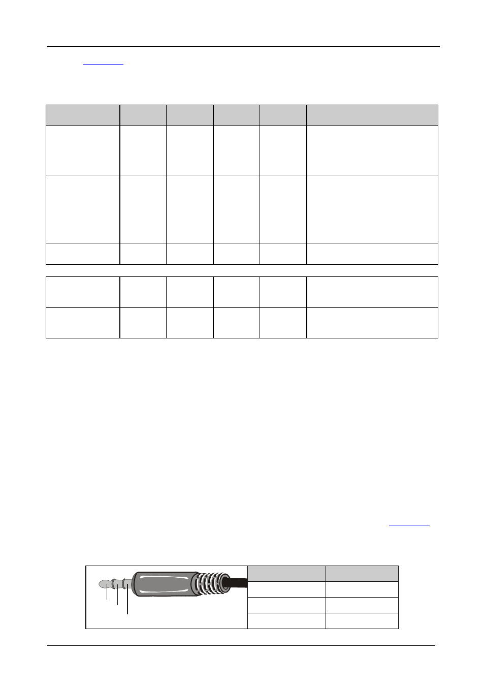
Installing a Remote Button
You can connect the remote 3.5mm mini jack to an external button for easy
on-line connection when the unit is installed, say, under the table.
defines the remote pinout:
Table 13: Remote PINOUT
PIN
Function
Left
LED
Right
Key switch
Gnd
Ground
L
R
Gnd