1 your tp-107avr xga/audio line transmitter, Your tp-107avr xga/audio line transmitter, Figure 2: tp-107avr xga/audio line transmitter – Kramer Electronics TP-107AVR User Manual
Page 11
KRAMER: SIMPLE CREATIVE TECHNOLOGY
Your Line Transmitter, Receiver and Presentation Controllers
8
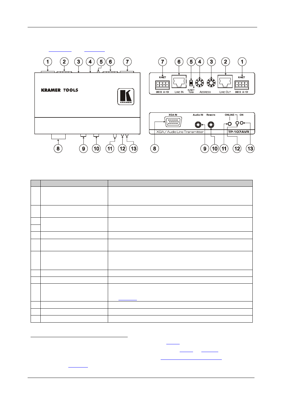
4.1 Your TP-107AVR XGA/Audio Line Transmitter
Figure 2: TP-107AVR XGA/Audio Line Transmitter
Table 4: TP-107AVR XGA/Audio Line Transmitter Features
#
Feature
Function
1 K-NET Terminal Block
Connector
Connect to the previous or next line transmitter or to a control device.
GND is for the ground connection; B (-) and A (+) are for RS-485,
and +12V is for powering the unit
2
LINE OUT RJ-45 Connector
Connects to
the LINE IN RJ-45 connector on the receiver
3
next line transmitter
ADDRESS Selectors
Rotate to select the address number
4
5 K-NET TERM Switch
Set the switch to ON to terminate the K-NET line with 120Ω
6 LINE IN RJ-45 Connector
Connects to
the LINE OUT RJ-45 connector on the previous line
transmitter
7 K-NET Terminal Block
Connector
Connect to the previous or next line transmitter or to a control device.
GND is for the ground connection; B (-) and A (+) are for RS-485,
and +12V is for powering the unit
8 XGA IN 15-pin HD Connector Connects to the XGA source
9 Audio IN 3.5mm Mini Jack
Connects to the audio source
10 Remote 3.5mm Mini Jack
Connect to an external button for easy on-line connection (for
example, when the unit is installed under the table). For the pinout,
see
11
Section 7
ONLINE Button
Press to access priority
12 ONLINE LED
Lights when gaining priority
13 ON LED
Lights when receiving power
1 The 12V DC power supply (not provided) is used to power the system (see
2 Using CAT 5 cable with RJ-45 connectors at both ends (the PINOUT is defined in
3 For example, the Kramer TP-122. You can download this user manual at:
http://www.kramerelectronics.com
4 From 1 to 256 (see