Your matrix switchers – Kramer Electronics VS-848 User Manual
Page 17
Your Matrix Switchers
KRAMER: SIMPLE CREATIVE TECHNOLOGY
14
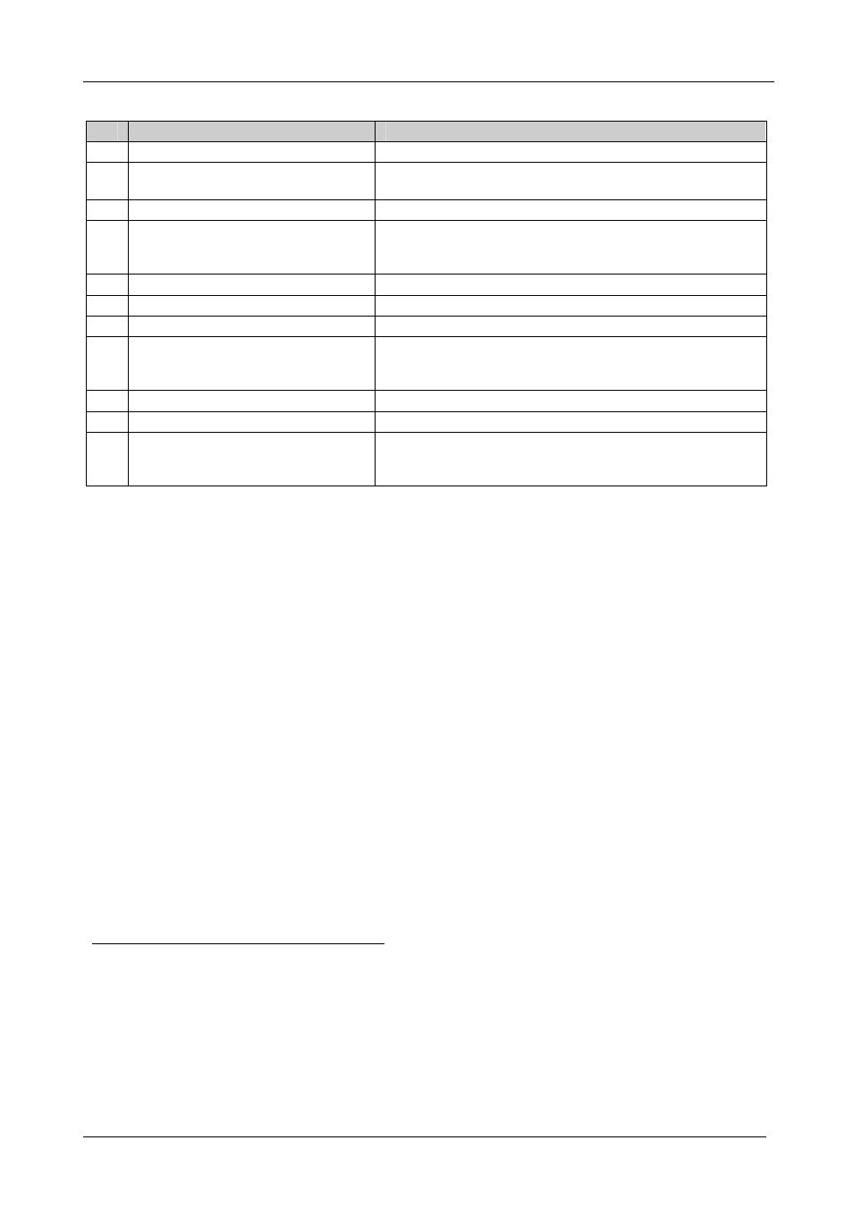
Table 4: Rear Panel VS-646 6x6 (VS-848 8x8) Features
#
Feature
Function
14
EXT. SYNC
BNC Connector
Connects to the external SYNC source
15
AUDIO INPUT
Terminal Block
Connectors
Connect to the audio sources
1
16
VIDEO INPUT
BNC Connectors
Connect to the video sources
1
17
SYNC
SELECT
Source
Selector
Button
Pushing in selects the (EXT) external sync source on the SYNC
connector; releasing selects the (IN 1) internal sync on the
VIDEO IN 1 connector
18
VIDEO OUTPUT
BNC Connectors
2
Connect to the video acceptors
1
19
AUDIO OUTPUT
RCA Connectors
Connect to the audio acceptors
1
20
RS-232
9-pin D-sub Connector
Connects to the PC or other Serial Controller
21 Setup DIP-switches
DIP 1, 2, and 3 for machine SELF ADDRESS #; DIP 4 for
RS-485 termination, DIP 5 for reply from switcher to PC,
DIP 8 for RS-232/RS-485 communication
22
RS-485
Connector
RS-485 port on detachable terminal block
23 Power Connector with
Fuse
AC connector enabling power supply to the unit
24
REMOTE IR
3.5mm Mini Jack
Connect to an external IR receiver unit for controlling the
machine via an IR remote controller (instead of using the front
panel IR receiver)
3
4.1 Using the IR Transmitter
You can use the
RC-IR2 IR transmitter to control the machine via the
built-in IR receiver on the front panel or, instead, via an optional external IR
receiver
4
. The external IR receiver can be located 15 meters away from the
machine. This distance can be extended to up to 60 meters when used with
three extension cables
5
.
Before using the external IR receiver, be sure to arrange for your Kramer
dealer to insert an internal IR connection cable
6
, which is required so that
the REMOTE IR 3.5mm connector can be used. Connect the external IR
receiver to the REMOTE IR 3.5mm connector.
Control the matrix switcher using the front panel buttons, or remotely via
the Kramer Infrared Remote Control Transmitter, via an external remote IR
receiver (optional), or via RS-485 or RS-232 serial commands transmitted
by a touch screen system, PC, or other serial controller.
1 For the VS-646, 6 inputs and 6 outputs; for the VS-848, 8 inputs and 8 outputs
2 For RGBS applications, one of the sync channels (H or V) may be used for the S channel
3 Optional. Can be used instead of the front panel (built-in) IR receiver to remotely control the machine (only if the internal
IR connection cable has been installed)
4 P/N: 95-0104050
5 P/N: 95-0103050
6 P/N: 505-70434010-S