Kramer Electronics VS-5x5 User Manual
Page 8
VS-5x5 –
O
verv
ie
w
5
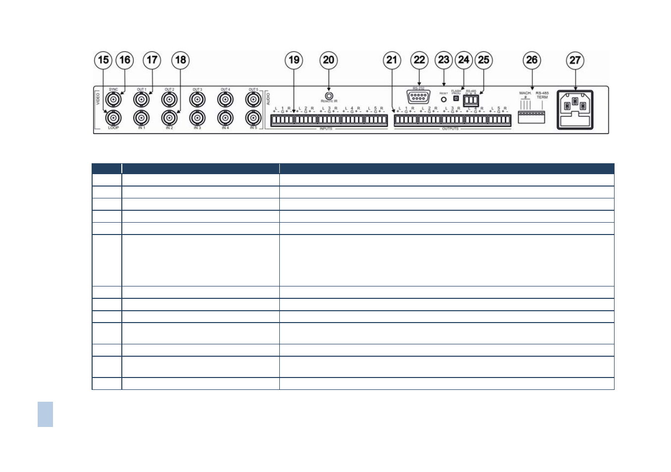
Figure 2: VS-5x5 Video Audio Matrix Switcher - Rear Panel
#
Feature
Function
15
LOOP BNC Connector
For looping the video inputs
16
SYNC BNC Connector
Connects to the external SYNC source
17
Composite BNC OUT Connectors
Connects to the composite video acceptors (from 1 to 5)
18
Composite BNC IN Connectors
Connects to the composite video sources (from 1 to 5)
19
INPUT Terminal Block Connectors
Connect to the balanced stereo audio sources (from 1 to 5)
20
REMOTE IR Socket
Covered by a cap. The 3.5mm mini
connector at the end of the internal IR
connection cable fits through this opening
Connect to an external IR receiver unit for controlling the machine via an IR remote
controller instead of using the front panel IR receiver
Optional. Can be used instead of the front panel (built-in) IR receiver to remotely control the
machine (only if the internal IR connection cable has been installed)
21
OUTPUT Terminal Block Connectors
Connect to the balanced stereo audio acceptors (from 1 to 5)
22
RS-232 9-pin D-sub (F) Port
Connects to the PC or the Remote Controller
23
RESET Button
Press to reset the unit to its original factory settings, or after firmware upgrade
24
FLASH PROG Button
Using a screwdriver if required, push in for “Program” to upgrade to the latest Kramer
firmware or release for Normal (the factory default)
25
RS-485 Terminal Block Port
Pin G is for ground connection; pins B (-) and A (+) are for RS-485
26 DIP-switches
DIP-switches
for setup of the unit (1, 2, 3 and 4 are for setting the Machine #; 5 is for the
Vertical Interval Source; 8 is for RS-485 termination)
27
Power Connector with Fuse
AC connector enabling power supply to the unit