5 setting the dip-switches, Setting the dip-switches, Figure 6: balanced stereo audio connection – Kramer Electronics VS-5x5 User Manual
Page 13: Figure 7: unbalanced stereo audio input connection, Figure 9: dip-switch settings, Section 5.4
10
VS-5x5 - Connecting the VS-5x5 5x5 Video Audio Matrix Switcher
5.4
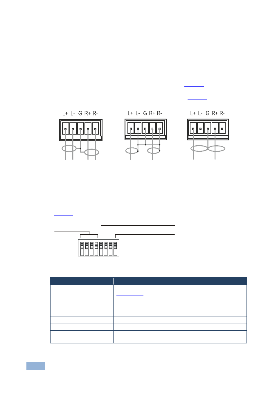
Connecting a Balanced/Unbalanced Stereo Audio
Input/Output
This section illustrates how to wire:
•
A balanced stereo audio connection, see
•
An unbalanced stereo audio input connection, see
•
An unbalanced stereo audio output connection, see
Figure 6: Balanced Stereo
Audio Connection
Figure 7: Unbalanced
Stereo Audio Input
Connection
Figure 8: Unbalanced
Stereo Audio Output
Connection
5.5
Setting the DIP-Switches
describes the factory default DIP-switches.
Figure 9: DIP-switch Settings
DIP#
Function
Description
1, 2, 3, 4
Machine #
Determines the position of a unit in the sequence (see
5 Vertical
Interval
Source
ON for Input # 1 (or programmable) Vertical Interval Source;
OFF for External Vertical Interval Source (default)
See
Section 11,
instruction # 7
6 Reserved
OFF
7 Reserved
OFF
8 RS-485
Termination
ON for RS-485 line termination with 120
Ω;
OFF for no RS-485 line termination
MACH #
RS-485 TERM
VERTICAL INTERVAL SOURCE
ON
1
8
7
4
6
3
5
2