1 using the ir transmitter, Using the ir transmitter, Table 2 – Kramer Electronics VP-8x8AK User Manual
Page 13
Your VP-8x8AK 8x8 VGA / UXGA / Audio Matrix Switcher
9
9
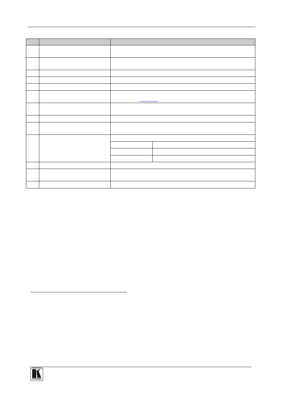
Table 2: Rear Panel VP-8x8AK 8x8 VGA / UXGA / Audio Matrix Switcher Features
#
Feature
Function
1
AUDIO INPUT 3.5mm Mini
Connectors
Connect to the unbalanced stereo audio acceptors (from 1 to 8)
2
AUDIO OUTPUT Terminal Block
Connectors
Connect to balanced stereo audio sources (from 1 to 8)
3
Power Switch
Illuminated switch for turning the unit ON or OFF
4
INPUT 15-pin HD Connectors
Connect to the video sources (from 1 to 8)
5
OUTPUT 15-pin HD Connectors Connect to the output acceptors (from 1 to 8)
6
PROG Button
Push in for “Program” to upgrade to the latest Kramer firmware via
RS-232 (see
), or release for “Normal” (the factory default)
7
RS-485 TERM DIP-switch
Use for RS-485 Termination
1
: ON for RS-485 Line Termination with
120
Ω; OFF for no RS-485 Line Termination
8
RS-232 9-pin D-sub Port
Connects to the PC or the remote controller
9
REMOTE IR Opening
2
Connects to an external IR receiver unit for controlling the machine via
an IR remote controller instead of using the front panel IR receiver
3
10 FACTORY RESET Button
Press to reset to factory default definitions
4
:
IP Address:
192.168.1.39
Mask:
255.255.255.0
Gateway:
192.168.1.1
11 ETHERNET Connector
Connects to the PC or other serial controller through computer networking
12 RS-485 Terminal Block Port
Pins B (-) and A (+) are for RS-485; Pin G (Ground) may be
connected to the shield of the cable if desired
13 Power Connector with Fuse
AC connector enabling power supply to the unit
4.1
Using the IR Transmitter
You can use the RC-IR3 IR transmitter to control the machine via the built-in IR
receiver on the front panel or, instead, via an optional external IR receiver
5
. The
external IR receiver can be located up to 15 meters away from the machine. This
distance can be extended to up to 60 meters when used with three extension cables
6
.
Before using the external IR receiver, be sure to arrange for your Kramer
dealer to insert the internal IR connection cable
7
with the 3.5mm connector
that fits into the REMOTE IR opening on the rear panel. Connect the external
IR receiver to the REMOTE IR 3.5mm connector.
1 The first and the last units on the RS-485 line should be terminated (ON). Other units should be unterminated (OFF)
2 Covered by a cap. The 3.5mm connector at the end of the internal IR connection cable fits through this opening
3 Optional. Can be used instead of the front panel (built-in) IR receiver to remotely control the machine (only if the internal
IR connection cable has been installed)
4 Turn the machine OFF using the power switch and then turn it ON while pressing the ETH Factory Reset button. The unit
will power up and load its memory with the factory default definitions
5 Model: C-A35M/IRR-50
6 Model: C-A35M/A35F-50
7 P/N: 505-70434010-S