Kramer Electronics VP-725NA User Manual
Page 17
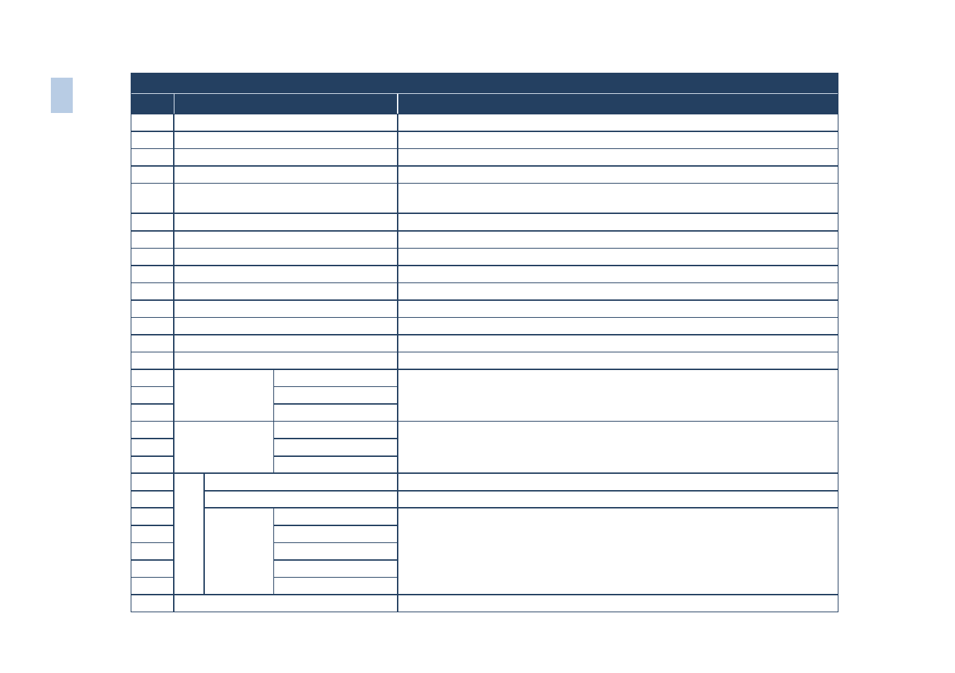
Rear Panel
#
Feature
Function
9
PROGRAM USB Connector
Connect to upgrade to the latest audio firmware
10
ETHERNET port
Connects to your LAN
11
RS-232 9-pin D-sub Connector
Connects to a PC or Serial Controller
12
MASTER OUT Terminal Block Connector Connects to the routed balanced audio channel
13
COND. MIC / DYN. MIC Button
Pushed in selects a dynamic microphone, released selects a
condenser microphone
14
MIC IN XLR Connector
Connects to the microphone
15
UXGA IN 15-pin HD Connectors
Connects to the UXGA (analog interface) graphics sources (from 1 to 4)
16
UXGA OUT 15-pin HD Connector
Connects to the UXGA (analog interface) graphics acceptor
17
CV IN BNC Connectors
Connects to the composite video sources (from 1 to 4)
18
CV OUT BNC Connector
Connects to the composite video acceptor
19
YC IN 4-pin Connectors
Connects to the s-Video (Y/C) sources (from 1 to 4)
20
YC OUT 4-pin Connector
Connects to the s-Video (Y/C) acceptor
21
HDMI IN Connectors
Connects to the HDMI sources (from 1 to 4)
22
HDMI OUT Connector
Connects to the HDMI acceptor
23
COMP Input
BNC Connector
G/Y
Connect to the component video source or RGB source from (1 to 4)
24
B/Pb
25
R/Pr
26
COMP
OUTPUT BNC
Connector
G/Y
Connect to the component video or RGB acceptor
27
B/Pb
28
R/Pr
29
SC
AL
ED
O
U
PU
TS
HDMI Connector
Connects to the HDMI acceptor
30
UXGA 15-pin HD Connector
Connects to the UXGA (analog interface) graphics acceptor
31
BNC
Connector
R/Pr
Connect to the component video or RGBHV acceptor
32
H
33
G/Y
34
V
35
B/Pb
36
Power Connector with FUSE
AC connector enabling power supply to the unit
12
VP
-72
5N
A
–
O
ver
vi
ew