Kramer Electronics VP-725NA User Manual
Page 15
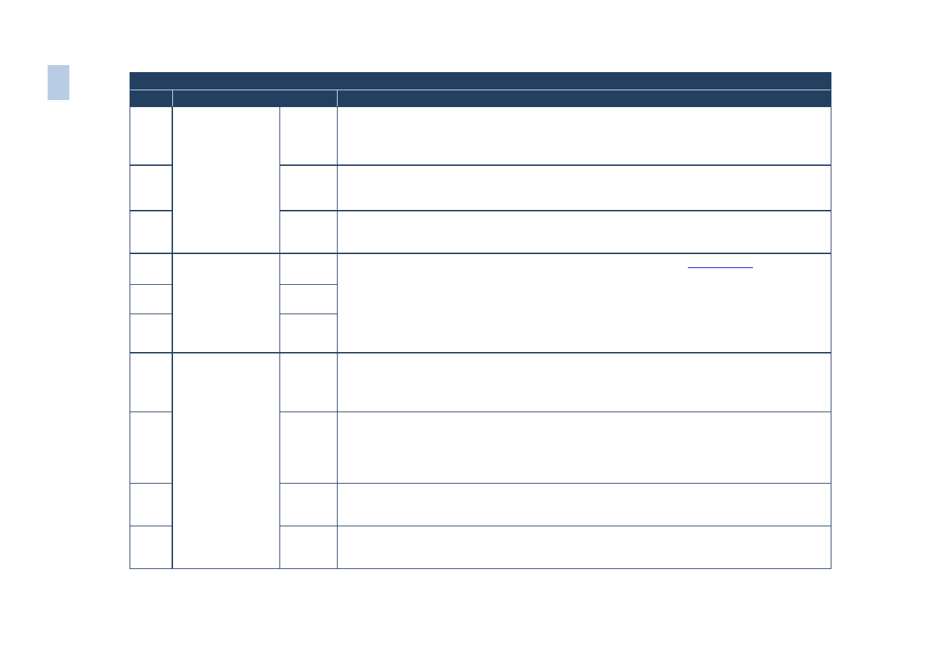
Front Panel
#
Feature
Function
20
MIC CONTROL
Button
Override Routes the signal from the microphone to the Master output instead of from the Line, whose
signal is blocked
When no MIC CONTROL button is selected, the audio input is routed to the MASTER output, ignoring the
Mic input
21
Mix
Routes the combined signals from the Mic and the Line to the Master output
Only one of the group buttons can be ON, or all buttons can be OFF (pressing a button will select that
button, and turn OFF the previously selected button. If the selected button is pressed, it will turn it OFF)
22
Talkover Routes the selected input to the output until an audio signal is detected on the microphone input.
When this happens the selected input is faded out (to be faded back in when no input is detected
on the microphone)
23
AUDIO LEVEL
Button
Line
Press this button and adjust the audio level using the –/+ buttons (see
Section 6.3.1
). The level is
displayed in the LCD Display and OSD
Only one of the group buttons can be ON, or all buttons can be OFF (pressing a button will select that
button, and turn OFF the previously selected button. If the selected button is pressed, it will turn it OFF)
Selecting OUT when the Audio Group button illuminates, lets you select the group (scrolling through CV,
YC, VGA, Component and DVI, displaying the selection on the LCD (and OSD when appropriate) using
the UP and DOWN buttons
24
Mic
25
Out
26
SELECTButtons
Video
Group
Select the Video Group operation mode; within each group, select which input (from 1 to 4) to
switch to the output. The selected input button within each group is illuminated. If the AUDIO
GROUP button is also illuminated, the audio follows the video
When selected, this button illuminates
27
Audio
Group
Press to select the Audio Group mode: within each group, select the audio input (from 1 to 4) from
each group for switching. If the VIDEO GROUP button is also illuminated, the audio follows the
video
The VIDEO GROUP and AUDIO GROUP buttons set can be pressed simultaneously or independently;
the SCALER and the MASTER OUTPUT buttons set can be pressed simultaneously or independently
28
Scaler
Select the Scaler mode: press an input button (1 of 21), to select the input to be scaled at the
SCALED OUTPUTS. The selected input button illuminates. If the MASTER AUDIO button is also
illuminated, the audio follows the video
29
Master
Audio
Press to select the Master Audio mode: press an input button (1 of 20), to select the audio input to
switch to the MASTER OUT terminal block connector. The selected input button illuminates. If the
SCALER button is also illuminated, the audio follows the video
10
VP
-72
5N
A
–
O
ver
vi
ew