2 connecting via a network hub, switch, or router, 3 configuring the ethernet port on the vp-31ksi, 1 using the front panel input selector buttons – Kramer Electronics VP-31KSi User Manual
Page 22: 2 the audio-follow-video and breakaway modes, Connecting via a network hub, switch, or router, Configuring the ethernet port on the vp-31ksi, Using the front panel input selector buttons, The audio-follow-video and breakaway modes, Table 5: button illumination descriptions
KRAMER: SIMPLE CREATIVE TECHNOLOGY
Operating the VP-31KSi Locally via the Front Panel Buttons
18
5.9.2 Connecting via a Network Hub, Switch, or Router
You can connect the Ethernet port of the VP-31KSi to the Ethernet port on a
network hub, switch, or router, via a straight through cable with RJ-45 connectors.
The VP-31KSi Ethernet port has to be configured to be compatible with your
network (see
Section 5.9.3
5.9.3 Configuring the Ethernet Port on the VP-31KSi
To configure the Ethernet port on the VP-31KSi, use the K-Upload software
6
Operating the VP-31KSi Locally via the Front Panel Buttons
. For
instructions on using the K-Upload software, refer to the K-Upload Software
Guide.
Powering up the VP-31KSi recalls the previous settings (that is, the state of the
unit when it was powered down) from the non-volatile memory.
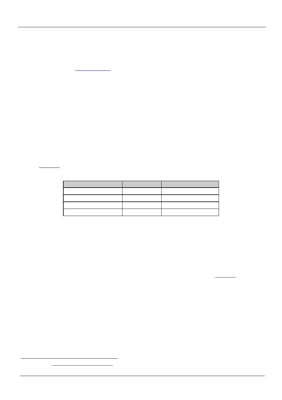
6.1 Using the Front Panel INPUT SELECTOR Buttons
describes the input selector button illumination descriptions.
Table 5: Button Illumination Descriptions
Button Color
Selected Input
Input Signal Detected
Red (video and audio)
Yes
No
Green (video)
No
Yes
Purple (video)
Yes
Yes
Button does not light
No
Yes or no
When a video input signal is detected, the button lights green. No audio signal
detection is performed.
When an input is selected (whether video or audio) and an input signal is detected,
the button lights red.
When a video signal is detected and the input is selected, the button lights purple.
To switch an input to the output, press one of the three front panel INPUT
SELECTOR buttons. The INPUT SELECTOR button lights (see
) and
switches the input simultaneously to both the VGA and CAT 5 TP outputs.
6.2 The Audio-Follow-Video and Breakaway Modes
When the VP-31KSi operates in audio-follow-video mode, all operations relate to
both the video and audio. When in this mode, both the VIDEO and the AUDIO
buttons are lit.
1 Available fro